Vintage Radio Restoration Guide
Introduction
Restoring a vintage radio is more than replacing defective parts. Each set is a historical object, a technical device and often also a piece of furniture. A good restoration should respect all three aspects.
This guide describes the general approach used for many of the radios shown on this site. It is not intended as a strict repair manual for a specific model. Every radio is different, and work on tube equipment requires electrical knowledge, patience and respect for high voltages.
The aim is to make a radio safe, reliable and understandable while preserving as much of its original character as possible.
Philosophy: Repair, Restoration and Conservation
Before any work begins, the goal of the project should be clear. Not every vintage radio should be treated in the same way. A common household receiver from the 1950s, intended to be used again from time to time, may justify a different approach than a rare, historically important and very original set.
The aim is not always to make a radio look factory-new. In many cases, the better goal is to keep it electrically safe, technically reliable and historically honest.
Repair
A repair focuses mainly on restoring basic function. Defective or unsafe parts are replaced, but the work is usually limited to what is necessary.
This approach is suitable for radios that are intended to play again, but where absolute historical accuracy under the chassis is not the main priority. Modern components may remain visible, as long as the work is clean, safe and reversible where possible.
Restoration
A restoration goes further than a simple repair. The goal is not only to make the radio work again, but also to preserve its appearance, character and long-term reliability.
This may include replacing known failure parts preventively, cleaning the chassis, renewing capacitors and electrolytics, repairing the cabinet, replacing damaged speaker cloth, restringing the dial drive or performing a careful alignment.
For many of the radios on this site, this is the preferred approach: the set should be safe and usable again, but it should still look and feel like an old radio, not like a modernized object.
Conservation
Some radios are better conserved than restored. This applies especially to very rare, historically important or exceptionally original sets.
In such cases, the goal is maximum preservation of original material. The radio may be cleaned and stabilized, but the electronics are left largely untouched. If unsafe original components remain in place, the radio should not be operated from the mains. It then becomes a preserved historical object rather than a working appliance.
This approach is closest to museum conservation. Function is less important than authenticity.
A balanced approach
In practice, the best solution is often somewhere between these categories. A radio may receive modern electrical parts for safety and reliability, while the visible appearance and historical character are carefully preserved.
Where appearance matters, modern capacitors can be hidden inside the original capacitor bodies. This keeps the chassis visually close to its original state while still improving electrical safety.
A badly repaired radio with hanging wires, bypassed safety components or randomly installed parts loses both technical reliability and historical value. Good restoration should be clean, understandable, safe and respectful of the original construction.
A Practical Skill, Not Rocket Science
Vintage radio restoration can look intimidating at first, especially when the chassis is full of old components, point-to-point wiring and unfamiliar tube circuits. But for many ordinary household radios, the work is not black magic.
You do not need to design microwave filters, read a Smith chart or calculate complex impedances to bring a typical tube radio back to life. Most practical restoration work is much more down-to-earth: understanding basic electrical principles, reading a schematic, recognizing unsafe parts, replacing aged components carefully and making clean solder joints.
The soldering work is also very different from modern electronics. These radios were built with relatively large components, solder tags and point-to-point wiring. This is not the same as repairing tiny lead-free SMD components under a microscope.
Of course, this does not mean that the work is harmless. Tube radios contain high voltages and must be treated with respect. A good technical and electrical understanding is necessary, especially around the mains input and power supply.
The encouraging part is that radios from the same period often follow very similar principles. Power supply, audio amplifier, detector, IF stages, tuning section and loudspeaker circuits appear again and again in different forms. The typical faults also repeat: leaky capacitors, dried electrolytics, dirty switches, drifted resistors, brittle wiring and previous repairs.
Once these patterns are understood, restoration becomes less mysterious. It is careful, methodical work — not rocket science, but still real electrical work.
Scope of This Guide
This guide gives an overview of the restoration approach used for the radios shown on this site. It describes the typical workflow, the main safety considerations and the decisions that occur again and again during vintage radio restoration.
It is not intended to be a complete textbook on radio repair, cabinet making or electronic alignment. Some tasks, such as reproducing missing knobs, repairing broken Bakelite, replacing veneer, restringing complex dial drives or performing a full RF alignment, can become specialized projects of their own.
The purpose of this page is therefore to show the principles: inspect carefully, work safely, preserve what can be preserved, replace what must be replaced and avoid unnecessary intervention.
Initial Inspection and Safety
Before a vintage radio is cleaned, repaired or powered up, it should be inspected carefully. This first inspection is not only a technical step, but also a safety measure.
Old radios can contain damaged mains cables, brittle insulation, leaking capacitors, previous repairs, loose wires, missing backs, incorrect fuses or components that have been bypassed. Some faults are visible immediately, others only become clear after comparing the set with its schematic.
A radio should not simply be plugged in “to see if it works”. Failed electrolytic capacitors, short circuits or damaged wiring can destroy expensive parts such as the mains transformer, rectifier or output transformer. In the worst case, they can also create a shock or fire hazard.
Documentation and service data
Before work begins, the radio should be documented in its original condition. Photographs should be taken of the chassis from above and below, the wiring around the power supply, tube sockets, loudspeaker connections, dial cord, antenna connections and any labels inside the cabinet.
The schematic and, if available, the original service documentation should be researched before electrical work starts. Useful sources include service manuals, tube data books, collector websites, Radiomuseum entries and manufacturer documentation. See also the Schematic Sources section.
However, the actual radio should always be compared with the schematic. Production changes, export versions and previous repairs can lead to differences between the diagram and the set on the bench.
Special attention should be paid to:
- tube types and tube positions
- mains voltage selector setting
- fuse rating
- power transformer and rectifier circuit
- electrolytic capacitors
- paper capacitors connected to critical points
- antenna and earth connections
- speaker and output transformer wiring
- previous repairs or non-original modifications
- dial cord routing
- labels, stamps and serial numbers
- damaged or missing parts
This documentation is useful during the restoration and also helps future owners or repairers understand what was done.
Mains safety
The mains side of the radio must be checked before any power is applied. The power cord, plug, strain relief, voltage selector, fuse holder and mains switch should be inspected carefully.
Cracked rubber wiring, exposed conductors, missing strain reliefs or improvised mains connections must be corrected before operation. Fuses should have the correct value and type. A fuse that is too large, or one that has been bypassed, removes an important layer of protection.
AC/DC sets and transformerless radios require particular care. In such designs, one side of the mains may be connected directly or indirectly to the chassis. Depending on the plug orientation and circuit design, accessible metal parts can become dangerous. Work on these sets should only be done with proper isolation and a clear understanding of the circuit.
Do not power up too early
When a radio is first acquired, it should not be powered up just to see what happens. The first inspection is intended to find obvious safety problems before mains voltage is applied.
Damaged mains wiring, leaking electrolytic capacitors, short circuits, incorrect fuses or poor previous repairs can cause serious damage within seconds. Expensive and often hard-to-replace parts such as the mains transformer, rectifier or output transformer may be destroyed by an uncontrolled test.
The first power-up should therefore be treated as a separate step after inspection, documentation and the most critical safety-related repairs have been completed.
High voltage and stored charge
Tube radios contain high voltages. Even after the set has been switched off, electrolytic capacitors may retain charge for some time. Before touching the circuit, the power must be disconnected and the capacitors should be discharged safely.
Measurements inside a powered radio should be made carefully, with insulated probes and one hand kept away from the chassis where possible. Test leads should be arranged so that they cannot slip or short adjacent terminals.
The loudspeaker should normally remain connected during operation if the output stage and output transformer require it. Operating a tube output stage without a proper load can damage the output transformer.
First inspection checklist
During the initial inspection, the following points should be checked:
- Is the mains cable safe?
- Is the correct fuse installed?
- Is the voltage selector set correctly?
- Is the back cover present and secure?
- Are any wires loose, burnt or brittle?
- Are there signs of overheating?
- Are electrolytic capacitors leaking or swollen?
- Are paper capacitors cracked, melted or leaking wax?
- Has the radio been modified by a previous repair?
- Are the tubes correct and in the right positions?
- Is the loudspeaker connected?
- Are the dial cord and tuning mechanism intact?
- Are there signs of corrosion, moisture or insect damage?
Final thought
The first inspection often decides the direction of the whole restoration. It shows whether the radio is a simple repair candidate, a careful restoration project or a set that should mainly be conserved.
Taking time at this stage prevents damage, improves safety and helps preserve the history of the radio.
Cleaning
Cleaning is an important part of radio restoration, but it should never be treated as simple cosmetic work. Dust, nicotine residue, grease, corrosion and old dirt can make a radio look poor, but they can also hide technical problems, cause bad contacts or contribute to leakage paths in high-impedance circuits.
The first step should always be gentle and dry. Loose dust can be removed with a soft brush, a small vacuum cleaner and patience. This also gives time to inspect the chassis, wiring, tube sockets, coils, transformers and mechanical parts before anything is disturbed.
A useful rule is: Clean first for preservation and inspection, not for shine.
Chassis cleaning
The chassis should normally be cleaned carefully and in small steps. Dry brushing is usually the safest starting point. Cotton swabs, wooden sticks and a soft toothbrush can help in corners and around tube sockets.
Grease and nicotine residue may require a mild cleaner or isopropyl alcohol, but liquids should be used sparingly. IF transformers, coils, tuning capacitors, paper labels, dial mechanisms and painted markings must be protected.
Water-based washing of a complete chassis is sometimes described by restorers, but it is not a good default method and should only be considered if the chassis has been stripped and can be dried completely.
The aim is not to make the chassis look new. A clean, stable and readable chassis is better than an over-polished one with lost markings, damaged plating or rubbed-off labels.
Dial scales and printed glass
Dial scales are among the most fragile parts of many vintage radios. The printing is often on the rear side of the glass and can be much less stable than it looks. Even water, glass cleaner or light rubbing can remove station names or scale markings permanently.
Before cleaning a dial glass, it is good practice to take detailed photographs or scans. Cleaning should begin only on a small hidden area. If the printing is unstable, it may be better to remove only loose dust with a very soft brush and leave the rest untouched.
On many radios, a slightly aged but original dial scale is far more valuable than a perfectly clean one with missing lettering.
Cabinets
Cabinets should be cleaned according to their material and condition.
Wooden cabinets often have aged lacquer, veneer, stains and small traces of use. These should not automatically be removed. Mild cleaning may be enough if the finish is still stable. If the surface is badly damaged, deeper cabinet restoration may be necessary, but this should be considered a separate restoration step rather than ordinary cleaning.
Bakelite and plastic cabinets can often be cleaned with mild soap and water, followed by careful drying. Strong solvents should be avoided, especially on plastics, painted surfaces, logos and trim parts. Early plastics and rubber parts can react unpredictably to heat, solvents and aggressive polishing.
Metal trim, brass parts and knobs may be polished if appropriate, but original patina should not always be removed completely. On a historically interesting set, traces of age are part of the object.
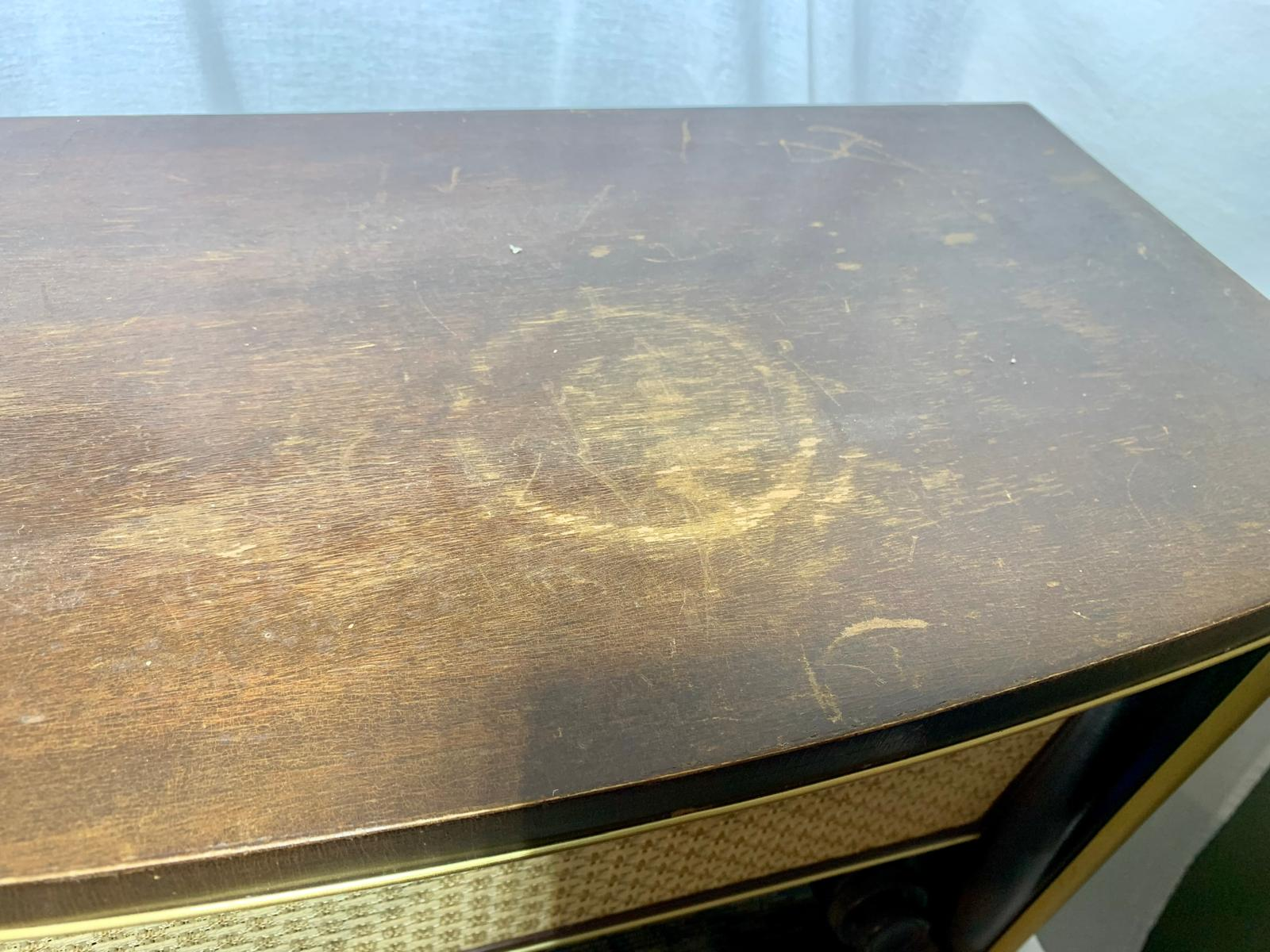
Typical cabinet damage: water rings
A very typical kind of damage on wooden radio cabinets are circular water marks on the top surface. These marks were often caused by flower pots, vases, glasses or other household objects placed directly on the radio. This also shows how these sets were used in everyday life: a large radio was not only a technical appliance, but also a piece of furniture in the living room.
Depending on the depth of the damage, such rings may affect only the old varnish or polish, but in more severe cases moisture has penetrated deeper into the finish or even into the veneer. For this reason, water rings are not only a cosmetic issue. They can also indicate lifted veneer, staining, swelling or damage to the original surface. In a conservation-minded restoration, these marks should first be assessed carefully. Minor traces of use may be kept as part of the history of the set, while more serious damage should be repaired sympathetically and without unnecessary over-restoration.
Controls and switches
Noisy potentiometers, dirty waveband switches and oxidized contacts are common problems. Contact cleaner can help, but it should be used deliberately and in small amounts. Spraying large quantities into every opening often causes more harm than good.
After cleaning, switches and controls should be operated several times to distribute the cleaner and remove oxidation mechanically. If a control is mechanically damaged or badly worn, cleaner alone will not repair it.
Speaker cloth and paper parts
Speaker cloth, paper labels, cardboard backs and tube-layout diagrams are often very fragile. They should be cleaned only very gently, usually with dry methods.
If the speaker cloth is torn, stained or brittle, replacement may be acceptable, but original cloth should be preserved whenever possible.
Labels and diagrams inside the cabinet should be photographed before cleaning. Once damaged, they are difficult to replace authentically.
Final thought
Good cleaning is restrained cleaning. The goal is to remove dirt that harms appearance, function or preservation, while keeping original material, markings and age-related character intact.
A vintage radio should look cared for, not artificially new.
Capacitor Replacement
Capacitors are among the most common failure points in vintage tube radios. Paper capacitors often become electrically leaky with age, and electrolytic capacitors can dry out, lose capacity or develop excessive leakage current.
Replacing these parts is not only about making the radio work again. It is also an important safety and reliability step.
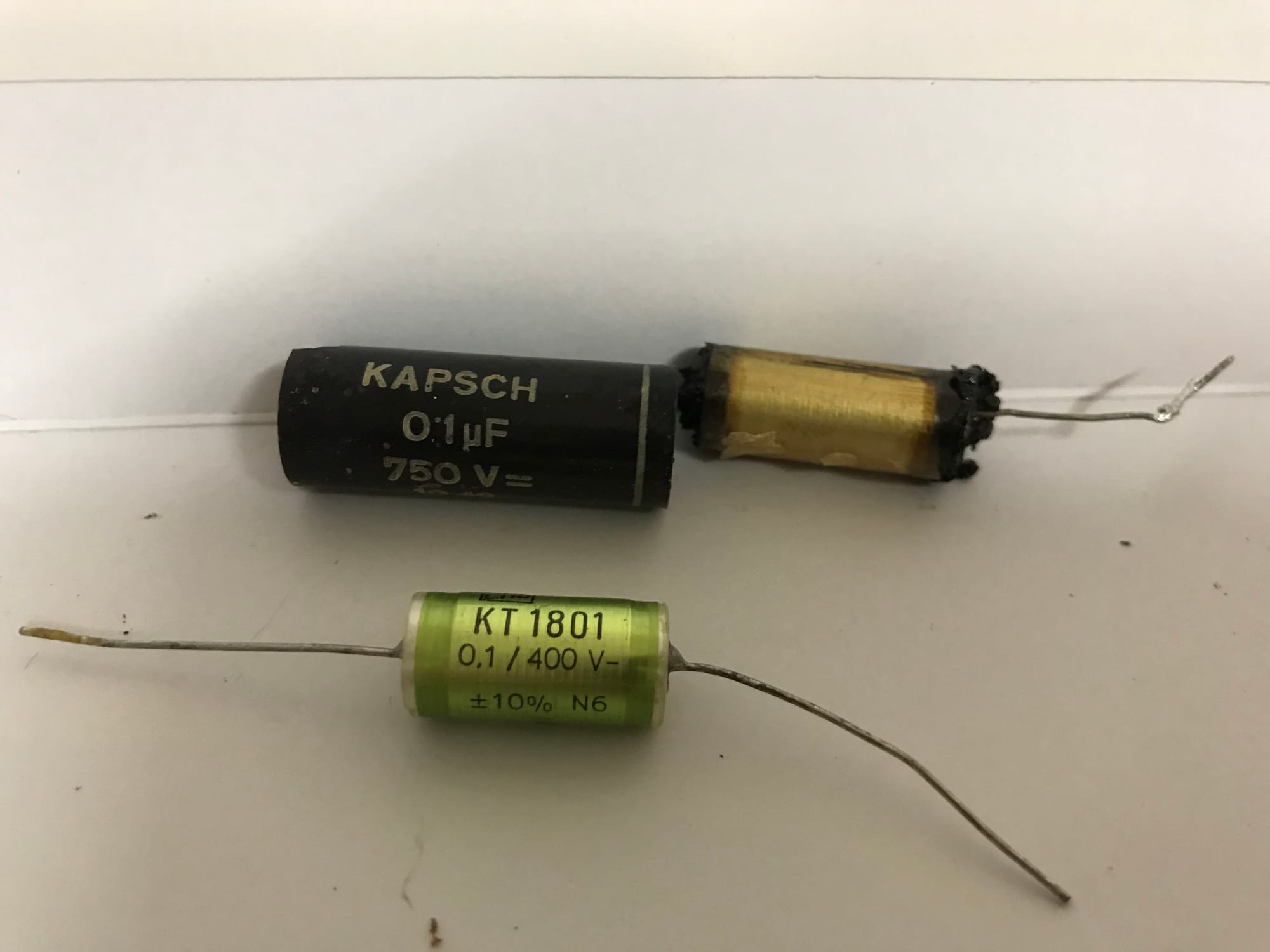
Paper capacitors
Wax-paper and paper-in-oil capacitors should be treated with suspicion, especially if they are connected to high voltage points. Even if they look acceptable from the outside, they may be leaky electrically.
One of the most important capacitors in many tube radios is the coupling capacitor between the audio preamplifier and the output tube. If this capacitor leaks DC voltage, the output tube can draw excessive current. This may damage the tube, the output transformer, the rectifier or the power transformer.
For this reason, paper capacitors in critical positions are normally replaced during restoration.
Electrolytic capacitors
Electrolytic capacitors in the power supply are also critical. Old filter capacitors may cause hum, overheating, rectifier stress or short circuits.
If the radio has not been powered for many years, applying full mains voltage to old electrolytics can be risky. In many restorations, the electrolytic capacitors are replaced or rebuilt before the first controlled power-up.
Original multi-section capacitor cans can often be preserved visually. The old can may be disconnected internally or carefully opened and fitted with modern capacitors inside. This preserves the original appearance while improving safety and reliability.
Safety capacitors
Capacitors connected directly across the mains or from mains to chassis must be replaced only with proper safety-rated types.
Across the mains, an X-rated capacitor is required. From mains to accessible metal parts or chassis, only suitable Y-rated safety capacitors should be used. Ordinary film capacitors are not appropriate in these positions.
This is especially important in AC/DC sets and other designs where the chassis may be connected to the mains circuit.
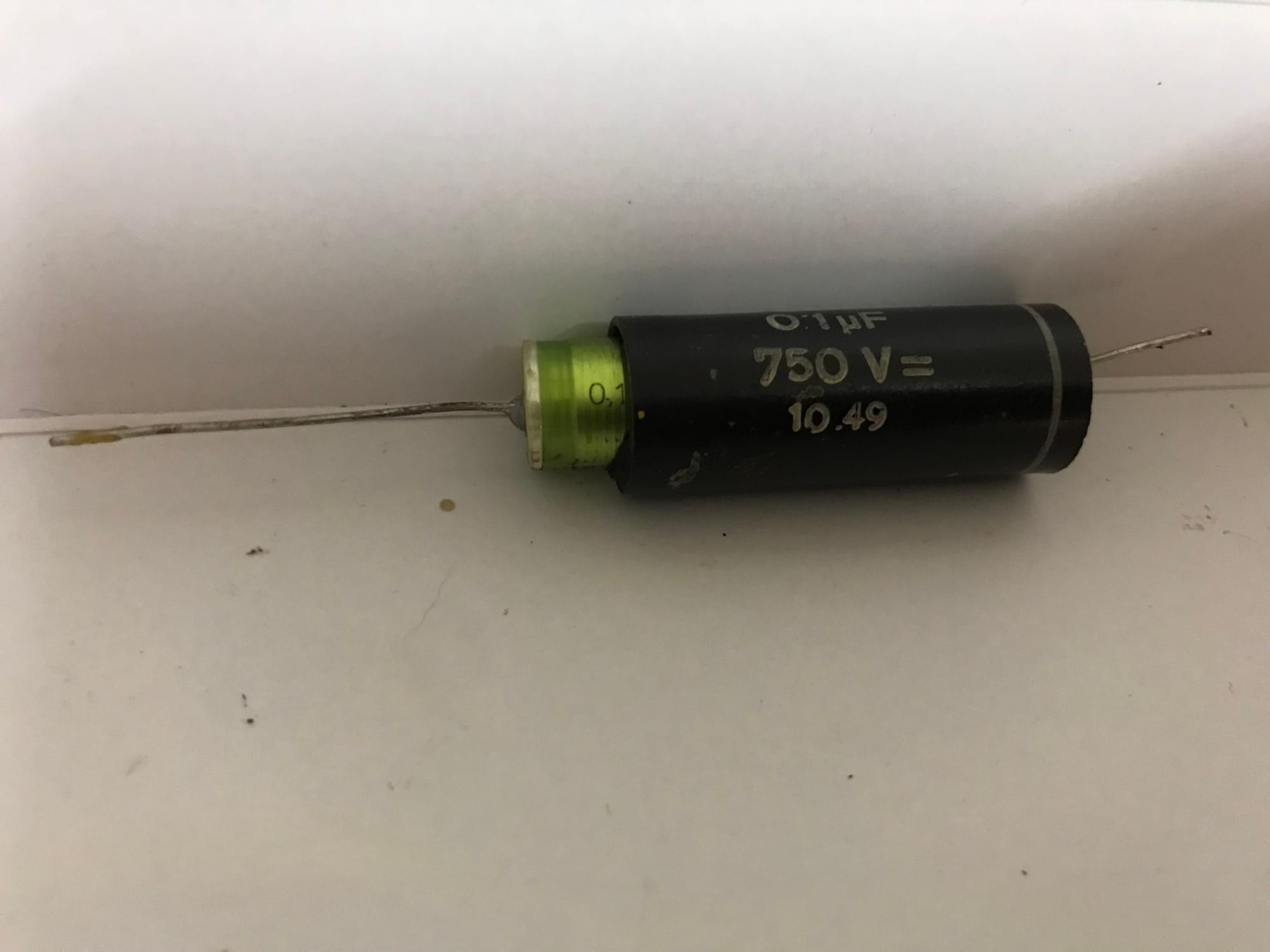
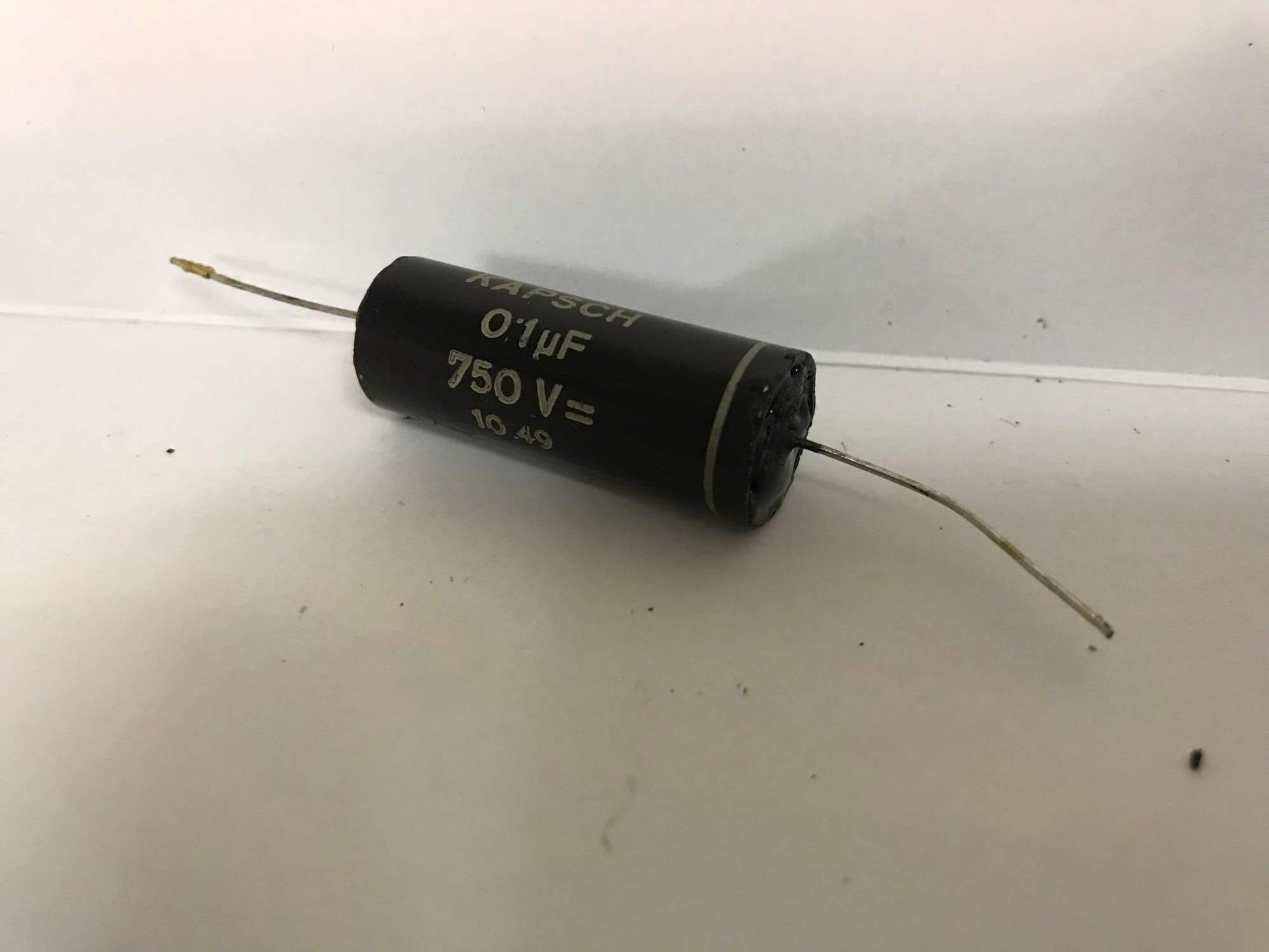
Re-stuffing original capacitor bodies
On the radios shown on this site, original capacitor bodies were preserved where possible. The old capacitor was opened, the defective internal material was removed, and a modern capacitor was installed inside the old body. The capacitor was then closed again carefully.
This method takes more time than installing modern yellow or blue capacitors directly under the chassis, but it helps preserve the historical appearance of the radio.
Re-stuffing is especially useful when the chassis is visible, when the radio is rare, or when the aim is a conservation-friendly restoration.
Replacement practice
Capacitors should be replaced with the same capacitance value or the nearest standard value, and with an equal or higher voltage rating. The circuit function must always be considered. In tuned RF and IF circuits, capacitor values can be critical and should not be changed casually.
It is good practice to replace components one at a time and check each connection carefully. Taking photographs before and during the work helps avoid mistakes.
Not every capacitor in a radio automatically needs replacement. Ceramic and mica capacitors are often more stable than paper capacitors and should usually be left in place unless there is a specific reason to suspect them.
Final thought
Capacitor replacement should be careful, documented and respectful of the original layout. The goal is not to modernize the radio, but to remove known failure points while preserving the original circuit and appearance as far as practical.
Resistors, Tubes and Other Components
After the capacitors have been addressed, other components should be checked carefully. A vintage radio is a system: replacing capacitors alone does not guarantee that the set is healthy.
Resistors
Carbon resistors can drift upward in value over time. This is especially common in high-value resistors and in parts exposed to heat. A resistor that has changed value may alter bias conditions, reduce gain, cause distortion or make alignment difficult.
Resistors should be checked against the schematic and replaced if they are clearly outside tolerance or show signs of overheating, cracking or mechanical damage.
When replacing resistors, the power rating and voltage stress must be considered. A modern resistor with the correct resistance value but too low a power rating is not a proper replacement.
Tubes
Tubes are often blamed first, but they are often not the main problem. Many radios still contain usable original tubes. A weak or defective tube can cause poor sensitivity, distortion, hum, low output or no reception, but tubes should be tested and diagnosed rather than replaced blindly.
The tube line-up should be compared with the schematic and the label inside the cabinet. Previous owners sometimes installed incorrect substitutes. In some cases this may work, but it can also lead to poor performance or damage.
Tube sockets should be inspected for corrosion, loose contacts and poor solder joints. A radio with intermittent crackling or dropouts may have dirty tube pins or weak socket contacts rather than a defective tube.
Rectifiers
Selenium rectifiers and old tube rectifiers deserve special attention. A weak rectifier may produce low B+ voltage, hum, overheating or poor performance. A failing selenium rectifier can also become hot and produce an unpleasant smell.
If a selenium rectifier is replaced with a silicon diode, the circuit may need an additional series resistor to keep the operating voltage close to the original value. A silicon diode usually has a lower voltage drop than a selenium rectifier.
The goal should not simply be to increase the voltage. The radio should operate within the voltage range intended by the manufacturer.
A good replacement that was also used for one of the radios on this site can be found in https://www.radiomuseum.org/forum/selengleichrichter_ersatz_durch_mosfet_schaltung.html
Loudspeaker and output transformer
The loudspeaker, field coil if present, and output transformer are important and sometimes difficult-to-replace parts. They should be inspected before operation.
Open windings, damaged speaker cones, rubbing voice coils and brittle speaker leads are common problems. The output transformer should be checked for continuity before prolonged testing.
Many radios require the loudspeaker to be connected during operation. Running the output stage without a proper load can damage the output transformer.
Dial lamps and scale illumination
Dial lamps are small parts, but they are often important for the correct electrical operation and appearance of the radio. The correct voltage and current rating should be used.
In some radios, dial lamps are part of the heater or current-limiting arrangement. Installing the wrong lamp can affect operation or stress other components.
The visual effect also matters. A warm, gentle illumination usually fits a vintage radio better than overly bright modern lighting.
Mechanical Parts
Mechanical problems are very common in vintage radios. Even if the electrical circuit is healthy, a radio will not be pleasant to use if the tuning drive, dial pointer, switches or pushbuttons are stiff, slipping or unreliable.
Dial cord and tuning mechanism
The dial cord is the cord that connects the tuning knob, pulleys, tuning capacitor and dial pointer. It translates the rotation of the tuning knob into the movement of the pointer across the scale.
Broken, missing or slipping dial cords can be one of the more frustrating mechanical jobs in radio restoration. The cord routing is sometimes surprisingly complex, with several pulleys, springs and multiple turns around the tuning shaft. Without documentation, it can take considerable patience to reconstruct the correct path.
If possible, the original service documentation should be consulted before replacing a dial cord. Many service manuals include a dial-cord diagram. If no diagram is available, detailed photos of an identical chassis can be very helpful. Existing cord routing should always be photographed before removing anything, even if the cord is already loose or partly broken.
The correct cord thickness and tension are important. Too little tension causes slipping; too much tension can stress pulleys, bearings or the tuning capacitor. The pointer position must also be set correctly after restringing, otherwise the radio may receive properly but show the wrong frequency on the scale.
Pulleys, bearings and lubrication
Hardened grease can make the tuning mechanism stiff. Pulleys, shafts and bearings should be cleaned carefully and lubricated only where appropriate.
Oil or grease should not be applied everywhere. Some parts were originally intended to run dry, and excess lubricant can attract dust, contaminate the dial cord or reach the tuning capacitor.
The tuning capacitor should move freely without scraping. Bent plates, dirt or mechanical stress can cause short circuits between the rotor and stator plates.
Pushbuttons and band switches
Band switches and pushbutton mechanisms can be complex. They often combine electrical contacts with mechanical latching parts. Dirt, oxidation and hardened grease can make them unreliable.
These mechanisms should be cleaned and operated carefully. Forcing a stuck pushbutton or waveband switch can break parts that are difficult or impossible to replace.
Contact cleaner may help with oxidized switch contacts, but it should be used sparingly and only where it can actually reach the contact surfaces. Mechanical problems should not be treated as electrical contact problems.
Final thought
Mechanical restoration requires the same patience as electrical work. A clean, smooth and correctly adjusted tuning mechanism makes a restored radio feel complete.
First Power-Up
The first power-up is one of the most important moments in a restoration. It should not be rushed. A radio that has not operated for decades may contain faults that are not visible from the outside.
Before applying power, the basic inspection should be complete, the mains wiring should be safe, critical capacitors should have been addressed and the correct fuse should be installed.
Before applying power
Before the first controlled power-up, the following points should be checked again:
- correct mains voltage setting
- correct fuse value
- safe mains cable and plug
- no loose wires or tools inside the chassis
- loudspeaker connected
- tubes installed in the correct positions
- electrolytic capacitors correctly wired
- no obvious short circuits
- power switch working
- chassis secured safely on the bench
If the radio uses an external loudspeaker, field coil or special connector, this must be understood before power is applied.
Controlled power-up
For the first controlled power-up, an isolation transformer, a variable transformer and a wattmeter are a very useful combination.
The isolation transformer improves safety during measurements. The variable transformer allows the mains voltage to be increased slowly and deliberately. The wattmeter shows whether the radio draws a reasonable amount of power.
The voltage should be increased step by step while observing the radio. Heater glow, B+ voltage, rectifier behavior, transformer temperature and total power consumption should all be checked.
If the power rises unexpectedly, or if there are signs of smoke, smell, excessive hum, arcing or overheating, the test should be stopped immediately.
A variable transformer alone is not a safety device. It does not provide isolation and it does not automatically limit current. Correct fusing, isolation and power monitoring remain important.
What to observe
During the first power-up, the radio should be watched closely. It should not be left unattended during early tests.
Useful observations include:
- input power
- heater glow
- B+ voltage
- rectifier behavior
- transformer temperature
- hum level
- audio output
- response to volume and tone controls
- reception on the available wavebands
A short successful test does not prove that the radio is fully reliable. It only shows that no immediate major fault appeared during this first controlled test.
Measuring voltages
After the radio has warmed up, important voltages should be compared with the schematic. Some deviation is normal, especially with modern mains voltage, modern replacement parts and meter differences.
However, large deviations should be investigated. High output-tube current, incorrect bias, low B+ voltage, excessive ripple or missing screen voltage can indicate faults that need correction before longer operation.
After the first successful test
If the first power-up is successful, the radio should still be treated cautiously. The set should be operated for increasing periods while observing transformer temperature, hum, stability and overall performance.
Controls and switches should be tested on all bands. Only after this should the restoration be considered electrically stable.
Final thought
The first power-up is not a moment of curiosity, but a controlled technical test. The purpose is not simply to see whether the radio still works, but to bring it back to life without damaging original parts.
Alignment
Alignment means adjusting the tuned circuits of the radio so that it receives correctly and performs as intended. This can include IF alignment, RF alignment, oscillator tracking and dial calibration.
Alignment should not be the first step in a restoration. A radio with leaky capacitors, drifted resistors, weak tubes or dirty switches cannot be aligned properly. Mechanical and electrical faults must be corrected first.
When alignment is necessary
Not every restored radio needs a full alignment. If the set receives well, the dial tracking is acceptable and no IF transformers or RF coils have been disturbed, it may be better to leave the alignment untouched.
Alignment may be necessary if:
- the radio has poor sensitivity
- stations appear at the wrong dial positions
- IF transformers have been adjusted by a previous repair
- RF or oscillator components were replaced
- the dial cord was replaced and the pointer position changed
- the radio was heavily rebuilt
- reception is weak despite correct voltages and good tubes
Service documentation
The correct alignment procedure should be taken from the service documentation whenever possible. IF frequency, signal injection point, adjustment order and dial settings vary between models.
Common IF frequencies such as 455 kHz, 460 kHz, 468 kHz or 472 kHz are often encountered, but assuming the wrong frequency can make the radio worse.
The schematic and service notes should therefore be checked before any adjustment is made.
Equipment
A proper alignment normally requires a signal generator and an output meter or another way to monitor the radio output. The signal level should be kept low enough to avoid overloading the receiver and the automatic gain control.
For FM radios, alignment can be more demanding. Ratio detectors, discriminator circuits and FM front ends require suitable equipment and a clear procedure. Random adjustment of FM coils can seriously degrade performance.
Do not adjust blindly
IF transformers and RF trimmers should not be turned just because they are accessible. Old cores can crack, and some adjustments are fragile or sealed. Once disturbed, it may be difficult to return them to the original setting.
Before adjusting anything, the original position can be marked carefully. Adjustments should be small, deliberate and reversible where possible.
Dial pointer and mechanical alignment
Electrical alignment and mechanical dial position belong together. If the dial cord has been replaced, the pointer must first be set according to the service instructions or known reference points.
A mechanically mispositioned pointer can make a correctly aligned radio appear wrong. Conversely, electrical misalignment should not be corrected by simply moving the pointer.
Final thought
Alignment is a fine adjustment, not a repair method for unknown faults. Done correctly, it can restore sensitivity, selectivity and dial accuracy. Done carelessly, it can make a working radio worse.
Cabinet Restoration
The cabinet is the part of the radio most people see first. It gives the set its character and often determines whether the radio appears neglected, preserved or over-restored.
Cabinet work should therefore be approached with the same care as electrical restoration. The goal is not always to make the cabinet look new. The goal is to make it stable, clean and visually appropriate for the age and style of the radio.
Wooden cabinets
Many European tube radios have veneered wooden cabinets. The veneer may be thin, and aggressive sanding can easily damage it. Before sanding or refinishing, the condition of the original surface should be assessed carefully.
If the original finish is only dirty or dull, cleaning and gentle polishing may be enough. If the finish is cracked, missing or badly damaged, refinishing may be justified.
On many radios shown on this site, the cabinet was cleaned and treated with several layers of hard oil. This gives the wood a warm appearance without making it look too modern or plastic-like.
Loose veneer should be glued before finishing. Missing veneer or damaged corners can be repaired, but the repair should match the original material and color as closely as practical.
Bakelite and plastic cabinets
Bakelite cabinets are durable but not indestructible. They can crack, chip or become dull over time. Mild cleaning and careful polishing can often improve the appearance significantly.
Strong solvents, excessive heat and aggressive sanding should be avoided. Early plastics can react unpredictably and may become cloudy, brittle or discolored.
Cracks or missing corners can sometimes be repaired with epoxy or other suitable materials. Such repairs may remain slightly visible, especially if the color cannot be matched perfectly. A visible but stable repair is often preferable to leaving a damaged cabinet untreated.
Speaker cloth
Speaker cloth has a strong effect on the appearance of a radio. If the original cloth is intact and only slightly dirty, it should usually be preserved. If it is torn, badly stained, brittle or missing, replacement may be appropriate.
A replacement cloth should match the period and style of the radio as closely as possible. A cloth that is too modern can change the visual character of the set.
When replacing speaker cloth, the old mounting method should be documented. The new cloth should be stretched evenly but not excessively.
Metal trim and decorative parts
Brass trim, escutcheons, knobs and decorative strips can often be cleaned and polished. However, polishing should be done carefully. Removing all patina can make parts look unnatural.
After polishing, brass parts may be protected with a thin clear lacquer such as Zapon lacquer, if appropriate. This helps preserve the polished appearance and slows down oxidation.
Painted or printed trim should not be polished aggressively. Lettering, station names and logos can be lost easily.
Knobs and controls
Knobs should be removed carefully and documented before cleaning. Some knobs are fixed with small screws, spring clips or friction fit. Forcing them can damage the knob or the control shaft.
Cleaning should be gentle, especially on painted or filled lettering. If the original markings are still present, preserving them is more important than achieving a perfect shine.
Back covers and labels
The back cover is an important part of many radios. It provides ventilation, safety protection and often carries technical information, warnings or tube layout diagrams.
Damaged backs should be repaired if possible. Missing backs are a safety issue, especially on AC/DC sets or radios with accessible live parts.
Labels, stamps and paper diagrams should be photographed and preserved. They are part of the history of the radio.
Final thought
Good cabinet restoration should support the character of the radio. A vintage radio should not look neglected, but it also does not need to look like it left the factory yesterday.
Traces of age can be part of the object. Damage, dirt and instability are not.
Typical Failures
Many vintage radios show similar faults. Knowing the typical failure points helps make the restoration more systematic.
This list is not a substitute for diagnosis, but it is a useful starting point.
Electrical failures
Common electrical failures include:
- leaky paper capacitors
- dried or shorted electrolytic capacitors
- drifted carbon resistors
- oxidized tube sockets
- dirty band switches
- noisy potentiometers
- weak or defective tubes
- failing selenium rectifiers
- brittle rubber wiring
- incorrect previous repairs
- open speaker field coils
- open output transformers
- defective dial lamps
- poor solder joints
Power supply faults should always be taken seriously. Excessive hum, overheating, smoke or a glowing rectifier can indicate a problem that may damage rare parts.
Mechanical failures
Common mechanical failures include:
- broken dial cords
- stiff tuning mechanisms
- hardened grease
- cracked knobs
- loose pulleys
- broken pushbuttons
- damaged dial pointers
- warped or missing back covers
- loose loudspeaker mounting
- damaged cabinet veneer
- cracked Bakelite
Mechanical problems should be repaired carefully. Forcing a stuck tuning mechanism or pushbutton assembly often causes more damage.
Cabinet and appearance issues
Typical cabinet and appearance issues include:
- dull or cracked lacquer
- missing veneer
- water stains
- nicotine residue
- torn speaker cloth
- corroded trim
- missing logos
- damaged dial glass
- rubbed-off scale markings
- broken plastic parts
The decision between cleaning, repair, restoration and conservation depends on the originality and rarity of the radio.
Previous repairs
Previous repairs are common. Some are well done, others are unsafe or poorly executed.
Examples include:
- modern capacitors installed untidily
- incorrect component values
- bypassed fuses
- wrong tube types
- replaced transformers
- improvised antenna sockets
- added switches or connectors
- cut wires
- solder joints made without proper mechanical support
Previous repairs should not automatically be reversed. If a repair is safe, technically correct and part of the history of the object, it may be reasonable to leave it in place. If it is unsafe or poorly done, it should be corrected.
Final thought
A vintage radio usually has more than one fault. Successful restoration depends on patience, documentation and a methodical approach.
Replacing random parts without understanding the circuit may make the radio worse. Careful inspection, measurement and comparison with the schematic usually lead to a better result.
Sources and Further Reading
General
Wumpus Welt der Radios – Wumpus-Kompendium
Comprehensive german-language restoration notes.
Phil’s Old Radios – First Steps in Restoration
Good practical introduction to the first steps before deeper restoration work. Especially useful for inspection, cleaning and the warning not to power up an unrestored radio too early.
Phil’s Old Radios – Replacing Capacitors in Old Radios and TVs
A useful beginner-friendly explanation of why old capacitors are such an important topic in radio restoration.
Phil’s Old Radios – Powering Your Radio Safely With a Dim-Bulb Tester
A useful description of a traditional simple current-limiting method. In this guide, a setup with isolation transformer, variable transformer and wattmeter is preferred, but the article remains useful background reading.
Phil’s Old Radios – Improving Safety and Reliability of AA5 Radios
Useful background on transformerless and hot-chassis safety issues. Although written around American AA5 radios, many of the safety principles are also relevant to European AC/DC sets.
Radiomuseum.org – How to Clean Dirty Dial Glasses of Earlier Radios
A good discussion of how easily dial-glass printing can be damaged. Especially useful as a reminder to photograph and test before cleaning.
Radiomuseum.org – Servicing Old Radios: Useful Tips
General restoration notes, including cleaning, documentation and component replacement.
Canadian Conservation Institute – Caring for Plastics and Rubbers
Useful conservation background for Bakelite, early plastics, rubber parts and other sensitive materials.
AntiqueRadios.org – Superheterodyne Alignment
A useful overview of the general alignment process for superheterodyne receivers.
Radio-Ghe – Gehäusereinigung bei alten Radios
German-language practical notes on cleaning old radio cabinets.
Allan's Virtual Radio Museum – Information for restorers
Schematics, Circuit Diagrams, Service Manuals
Many online schematic archives contain overlapping material, often originating from older printed collections such as Empfängerschaltungen der Radioindustrie or from manufacturer service documentation. They are valuable practical sources for restoration work, but not always independent from each other.
Radiomuseum.org
One of the most comprehensive online collections of historical radio data, including model information, technical details, photographs, schematics and related documentation.
Library of the Silesian University of Technology – Empfängerschaltungen der Radioindustrie
Digital scans of volumes 1–11 of Empfängerschaltungen der Radioindustrie, containing several hundred radio receiver schematics. This printed series appears to be one of the original sources behind many scans that later reappeared in other online schematic collections. Scan quality varies between volumes and pages.
Raupenhaus.de – Schematic Archieve (2010)
A preserved 2010 snapshot of the former Raupenhaus.de schematic archive, containing tons of technical documents, service manuals and circuit diagrams for vintage radios, televisions, measurement equipment and related electronics. The collection is available via the Internet Archive as a large ISO image (22.5 GByte) with an included index. Copyright status may vary between documents, so individual scans should be reused with care.
Jogis Schaltplanservice historischer Geräte
A freely accessible schematic archive for historical tube equipment, offering more than 6,500 circuit diagrams sorted by manufacturer and model. It is especially useful for locating service information for German, Austrian and European vintage radios, including many common and lesser-known brands.
GFGF – Gesellschaft der Freunde der Geschichte des Funkwesens
A German association dedicated to the preservation and research of radio and wireless-history material. The GFGF maintains a specialist archive, publishes the journal Funkgeschichte, and is a valuable reference source for historical radio technology, documentation, manufacturers, circuits and restoration research.
Anova
A large downloadable collection of European radio schematics, useful as a practical reference source when searching for circuit diagrams by manufacturer and model.
Elektrotanya
A large online archive of service manuals, schematics and technical documentation for radios and other electronic equipment. It can be a useful source for locating circuit diagrams and repair information for specific radio models.
RSP Italy
An Italian online archive for vintage radio schematics, including the Beitman Radio Schematics Collection and the Rider’s Radio Schematics Collection.