From Crystal Detector to Software Defined Radio
The Technical Development of Radio Receivers from the Beginning to the Present Day
1. The radio receiver as a technical problem
A radio receiver is not simply an audio device. Technically, it is a highly selective measurement and signal-processing system. At the antenna input, the wanted signal may be only a few nanovolts to microvolts, while nearby unwanted signals can be many orders of magnitude stronger. The receiver must select the wanted signal, reject interfering signals, compensate for frequency errors, minimise noise, and finally recover either analogue audio or a digital data stream.
The fundamental receiver parameters have remained surprisingly constant over more than a century:
- Sensitivity: the minimum input signal that can still be usefully received.
- Noise figure: the degradation of the signal-to-noise ratio caused by the receiver itself.
- Selectivity: the ability to reject adjacent-channel and out-of-channel signals.
- Dynamic range: the range between the weakest usable signal and the strongest signal the receiver can handle without overload.
- Large-signal behaviour: the ability to remain usable in the presence of strong local transmitters.
- Oscillator phase noise: especially important when strong adjacent signals are present.
- Intermodulation performance: often described by IP2, IP3, blocking and reciprocal mixing.
A useful approximation for the minimum detectable input power is:
Pmin ≈ −174 dBm/Hz + 10 log10(B) + NF + SNRmin
where B is the receiver bandwidth, NF is the noise figure and SNR_min is the minimum signal-to-noise ratio required by the demodulator. This simple relationship already shows one of the basic truths of receiver design: bandwidth, noise and modulation method determine what is technically possible.
2. The beginning: detector receivers, regeneration and vacuum tubes
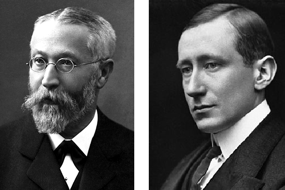
The earliest radio receivers were not “radios” in the modern entertainment sense. They were mainly instruments for wireless telegraphy. In 1909, Guglielmo Marconi and Karl Ferdinand Braun received the Nobel Prize in Physics for their contributions to the development of wireless telegraphy [1].
Early receivers used coherers, magnetic detectors and later crystal detectors. A crystal detector, for example galena with a fine wire contact, acts as a nonlinear rectifier. It can demodulate amplitude-modulated signals without any external power supply. However, it provides no real amplification, which makes it simple but insensitive.
The decisive technical step was the vacuum tube.
The Fleming valve, invented by John Ambrose Fleming in 1904, is generally regarded as the first practical thermionic valve / vacuum tube [2].
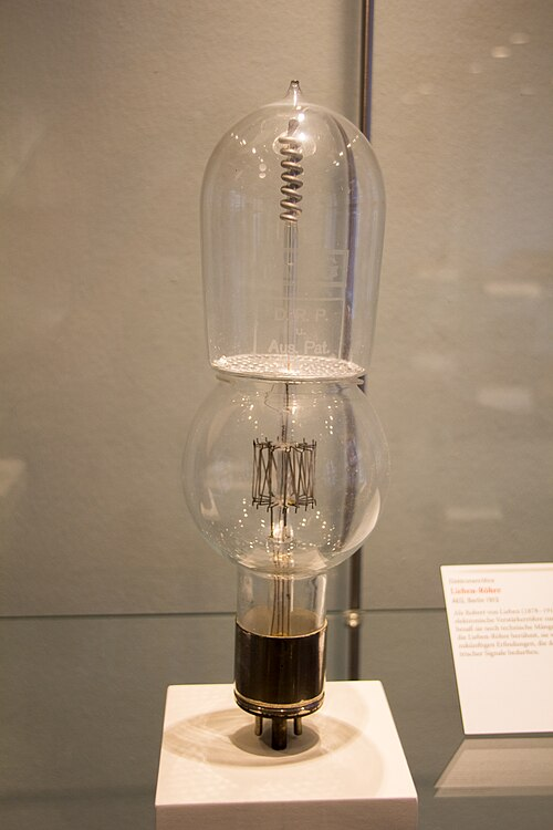
In the English-speaking literature, Lee de Forest’s Audion of 1906 is commonly cited as the first triode vacuum tube [3]. Almost in parallel, the Austrian inventor Robert von Lieben developed an early amplifier tube for long-distance telephony; this European line of development, continued with Eugen Reisz and Siegmund Strauss, became known as the Lieben valve [4, 5].
The tube made amplification, oscillation and mixing possible. With it, several important receiver architectures appeared.
Tuned Radio Frequency receiver / TRF receiver
In a TRF receiver, one or more RF stages are tuned directly to the received frequency. The complete selectivity is produced at the signal frequency itself. This is manageable at lower frequencies, but it becomes increasingly difficult as the frequency rises, because several tuned circuits have to track each other accurately.
Audion, regenerative receiver and the Meißner feedback principle
The regenerative receiver uses positive feedback to compensate part of the losses in the tuned circuit. As a result, the circuit behaves as if its Q were much higher: gain increases and the bandwidth becomes narrower. Just below the point of oscillation, this gives the receiver high sensitivity and selectivity. If the feedback is increased further, the receiver starts to oscillate and can be used to receive CW signals by providing a local beat note.
In English-language radio history, Edwin H. Armstrong is often presented as the central figure associated with regenerative reception, the superheterodyne receiver and FM broadcasting [6]. However, this view is somewhat Anglo-American in emphasis. In the European and especially German-speaking technical tradition, Alexander Meißner also deserves explicit mention. Working at Telefunken, Meißner applied positive feedback to vacuum-tube circuits in 1913 and developed a high-frequency generator based on this principle. The inductively coupled feedback oscillator is still known in German literature as the Meißner oscillator or Meißner feedback circuit [7].
This distinction is useful: Armstrong is closely associated with the regenerative receiver as a receiving circuit, while Meißner is particularly important for the deliberate use of positive feedback to generate continuous high-frequency oscillations. Both developments were essential for radio technology, because controlled feedback made it possible not only to increase receiver gain and selectivity, but also to build stable local oscillators and transmitters.
A historically important mass-produced example of a regenerative receiver is the German VE301 Volksempfänger, introduced in 1933 [9, 10].
Super-regenerative receiver
The super-regenerative receiver is a special form using periodically interrupted regeneration. It can achieve high sensitivity with very few components, but its selectivity and large-signal performance are limited, and it can radiate interference. It was later used mainly in simple remote controls, toys and low-cost VHF/UHF receivers.
3. The superheterodyne receiver: the dominant architecture of the 20th century
The superheterodyne receiver became the most important receiver architecture of the 20th century. Its principle is frequency conversion:
fIF = | fRF − fLO |
The incoming RF signal f_RF is mixed with a local oscillator signal f_LO and converted to a fixed intermediate frequency f_IF. This intermediate frequency can then be filtered and amplified using fixed, optimised circuits. The Engineering and Technology History Wiki describes the essence of the superheterodyne receiver as converting a high-frequency signal to an intermediate frequency by heterodyning it with a receiver-generated oscillator signal [11].
The great advantage is the separation of tuning and selectivity. The RF input circuits only need to provide preselection and image rejection, while the main channel filtering is performed at a fixed frequency.
Typical intermediate frequencies became:
- AM broadcast receivers: around 455 kHz
- FM broadcast receivers: 10.7 MHz
- Television and professional receivers: often several IF stages
- Shortwave communication receivers: frequently double or triple conversion
One inherent problem of the superheterodyne receiver is the image frequency. A mixer does not know which of two signals produced the same IF difference. Therefore, a signal at the image frequency can also be converted to the same IF.
fimage = fRF ± 2 fIF
A high first IF improves image rejection because the image is farther away from the wanted signal and easier to remove with RF filtering. A low IF, on the other hand, makes it easier to build very narrow and selective filters. For this reason, high-performance receivers often used double or triple conversion: a high first IF for image rejection, followed by one or more lower IFs for narrow filtering.
A classic high-quality superhet contains:
- Antenna input and impedance matching
- RF preselection
- Low-noise RF amplifier
- Mixer
- Local oscillator
- IF filter
- IF amplifier with AGC
- Demodulator
- Audio or data processing stage
Automatic gain control, AGC or AVC, was another important improvement. It reduces receiver gain for strong signals and increases it for weak signals. This keeps the IF level and audio volume relatively constant over a wide input range.
The invention history of the superheterodyne receiver is more complex than the simplified statement that it was invented by Edwin H. Armstrong. Several engineers arrived at closely related ideas during the First World War. Lucien Lévy in France filed patents in 1917 and 1918 covering essential parts of the superheterodyne principle. Armstrong independently developed the concept into a practical receiver and applied for his important U.S. patent, which was issued in 1920. In Germany, Walter Schottky also conceived a similar system independently and filed a German patent in 1918.
For a technical article, the most useful conclusion is not to treat the superheterodyne as the work of only one inventor. Lévy is important for patent priority and the early formulation of the principle, Armstrong for reducing the system to a practical and commercially influential receiver, and Schottky for the independent German development. The superheterodyne receiver was therefore less a sudden single invention than the convergence of heterodyne theory, vacuum-tube oscillators, wartime communication requirements and the need for better selectivity and gain [11, 12, 13].
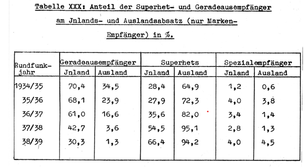
The technical superiority of the superheterodyne principle was also reflected very quickly in receiver production. A German AEG overview from 1940, Entwicklungstendenzen des Rundfunks by Dr. Lübeck, shows the rapid market shift from TRF receivers to superhets. Among branded receivers sold on the domestic market, the share of superheterodyne sets rose from 28.4 % in 1934/35 to 66.4 % in 1938/39. In export sales, the transition was even more pronounced: the superhet share increased from 64.9 % to more than 94 % over the same period, while TRF receivers almost disappeared from export models. This illustrates that the superheterodyne receiver was not only a theoretical improvement, but had become the dominant practical receiver architecture within only a few years.
4. AM, FM, CW, SSB and specialised demodulators
As modulation methods became more diverse, receiver demodulators became more specialised.
AM / envelope detection
In conventional amplitude modulation, the information is contained in the envelope of the carrier. A diode detector and a low-pass filter are sufficient. This made AM broadcasting simple, robust and inexpensive.
CW and SSB
Morse telegraphy and single-sideband voice require a beat-frequency oscillator or product detector. The receiver multiplies the IF signal with a locally generated carrier. Frequency accuracy and oscillator stability are much more critical than in simple AM reception.
FM
In frequency modulation, the information is contained in the instantaneous frequency of the carrier. The receiver needs amplitude limiting and a frequency discriminator, such as a Foster-Seeley discriminator, ratio detector, quadrature detector or PLL detector. FM offers excellent noise rejection when the signal is strong enough, but it also has a threshold effect: below a certain signal-to-noise ratio, reception quality collapses quickly.
FM stereo and RDS
FM stereo is not transmitted simply as separate left and right audio channels. The multiplex signal contains L+R in the baseband, L−R around a 38 kHz suppressed subcarrier and a 19 kHz pilot tone used to regenerate the stereo subcarrier. RDS uses a 57 kHz subcarrier, the third harmonic of the 19 kHz pilot tone [15]. With RDS, the receiver also became a data decoder, handling programme service names, alternative frequencies, traffic information and radiotext.
5. From vacuum tubes to transistors and integrated receiver ICs
The invention of the transistor in 1947 changed radio receiver design fundamentally [16]. Vacuum-tube radios were large, warm, mechanically sensitive and required heater power. Transistors enabled portable receivers, battery operation, lower power consumption and, eventually, large-scale integration.
The first transistor radios were not automatically better than good tube receivers. Early transistor circuits could suffer from higher noise, temperature drift, limited gain and modest large-signal behaviour. However, with silicon transistors, field-effect transistors and integrated circuits, these weaknesses were gradually reduced. Receivers became smaller, cheaper, more reliable and much more reproducible in mass production.
Important steps in this transition included:
- ferrite rod antennas for medium-wave portable receivers
- ceramic filters for low-cost IF selectivity
- varactor tuning instead of mechanical variable capacitors
- PLL synthesizers instead of free-running VFOs
- quartz references for frequency stability
- integrated IF amplifiers with AGC
- FM stereo decoder ICs
- RDS demodulator ICs
- microcontroller-controlled tuning and user interfaces
PLL synthesis made the receiver frequency digitally reproducible. The local oscillator was no longer a purely free-running tuned circuit, but was locked to a stable crystal reference by a phase-locked loop. This enabled station memories, scanning, digital frequency displays and more stable communication receivers. At the same time, oscillator phase noise became an important quality parameter. A receiver with poor oscillator purity can become effectively deaf in the presence of strong adjacent signals, even if its static sensitivity looks good.
Typical examples of this IC-based receiver generation include IF amplifier ICs with AGC, such as the Motorola MC1350, FM stereo decoder ICs such as the MC1310 or LM1310 family, RDS demodulators such as the Philips SAA6579 or ST TDA7330B, and PLL tuning synthesizers such as the Philips SAA1057. These devices illustrate how more and more receiver functions moved from discrete transistor circuits into specialised integrated circuits. Functions that previously required many individual components could now be implemented with a few compact and well-defined ICs.
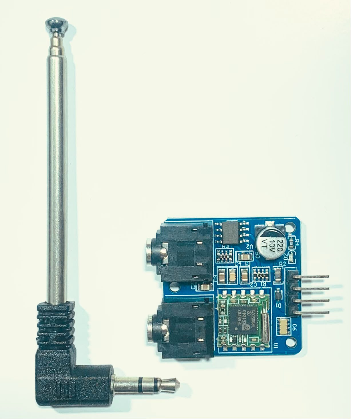
A later and very compact example of this development is the Philips/NXP TEA5767 [17, 18]. It is not a DSP receiver and not an SDR, but it is a good representative of the late highly integrated analogue FM receiver generation. Unlike earlier specialised ICs that implemented only one receiver function, such as IF amplification, stereo decoding or PLL tuning, the TEA5767 is essentially a complete electronically tuned FM stereo receiver in one chip. It includes integrated IF selectivity and FM demodulation and can be controlled by a microcontroller over an I²C or 3-wire bus. Devices such as the TEA5767 show how the classical FM receiver became a small, digitally controlled module: the RF and IF signal path remained analogue in principle, but tuning, search functions, status readout and the user interface were handled by digital control logic.
A typical TEA5767 module is therefore not very different in purpose from a traditional small FM radio, but its implementation is radically more compact. What once required tuned coils, variable capacitors, IF transformers, discriminator circuits and a separate stereo decoder could now be reduced to a small module with a chip, a reference crystal, a few external components and a serial control interface.
6. High-performance analogue communication receivers
While domestic broadcast receivers were optimised for comfort and audio quality, communication receivers were optimised for selectivity, frequency stability and large-signal performance.
Typical features of high-grade analogue receivers included:
- multiple RF preselection circuits
- double or triple conversion
- crystal filters with different bandwidths
- mechanical filters
- product detector for SSB and CW
- notch filter
- noise blanker
- passband tuning
- preselector
- switchable preamplifier and attenuator
- synchronous detector for AM
A good analogue receiver was therefore not defined only by the number of active devices. It was defined by filter quality, oscillator stability, mechanical construction, shielding, layout and RF discipline. Especially on shortwave, large-signal behaviour can be more important than nominal sensitivity. A receiver that can hear −130 dBm in the laboratory but overloads in the presence of strong broadcast stations is less useful than a slightly less sensitive but more robust design.
This analogue communication-receiver tradition is important because many of its design goals did not disappear with digital technology. Preselection, oscillator quality, dynamic range, intermodulation performance and carefully chosen bandwidths remain essential even in modern DSP and SDR receivers. The implementation changed, but the RF problems did not.
7. DSP: digitising the intermediate frequency
Before the full SDR concept became common, many receivers introduced DSP at the IF or audio stage. The RF part often remained conventional: preselector, mixer, oscillator and IF. After that, a digital signal processor took over functions that had previously been implemented with analogue circuits.
Typical DSP functions include:
- IF filtering
- notch filtering
- demodulation
- AGC
- noise reduction
- automatic carrier tracking
- spectrum display
- digital audio filtering
- signal-quality measurement
- tuning assistance and seek functions
The advantage of digital filters is repeatability. A digital FIR or IIR filter does not age, drift or require mechanical alignment. Very narrow CW filters, variable SSB bandwidths and adaptive notch filters became practical even in compact equipment.
This development also appeared in highly integrated broadcast receiver ICs. A representative example is the Silicon Laboratories Si4732 family, introduced in the late 2000s and later accompanied by related Si4735/Si4737 variants [19]. The Si4732 is a digital CMOS AM/FM/SW/LW/RDS receiver IC. It integrates the complete broadcast receiver chain from antenna input to digital audio output and uses a digital low-IF architecture. In such devices, the RF input and some analogue functions still exist, but many receiver tasks — filtering, demodulation, signal-quality measurement, tuning control and audio processing — are performed internally by digital signal processing.
This is an important architectural transition. The TEA5767 still represents the compact, digitally controlled analogue FM receiver. The Si4732/Si4735 generation represents the move toward the “radio as an internal DSP system”. The user may still see only a small radio module, but inside the chip the receiver is no longer built mainly from visible analogue filter and detector stages. Instead, much of the selectivity, demodulation and control logic is implemented in digital circuitry and firmware.
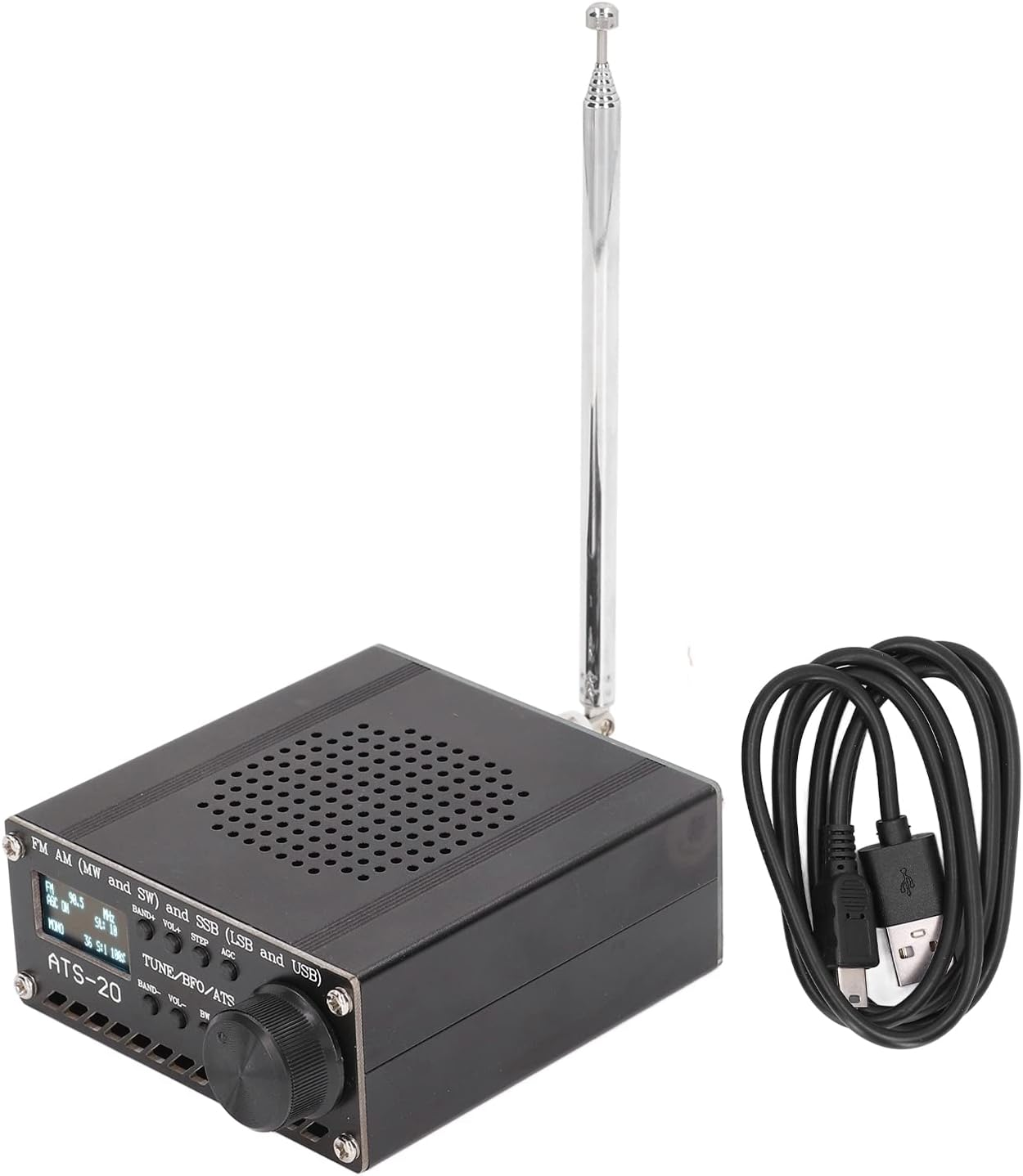
A modern hobby example is the ATS-20 class of small all-band receivers. These receivers are commonly built around Si4732 or related Si47xx chips and combine the radio IC with a microcontroller, display, rotary encoder and firmware. Depending on the exact chip, firmware and patches used, such receivers can cover FM, longwave, medium wave and shortwave, and some versions also offer SSB reception with BFO control [20, 21]. Technically, they are not SDRs in the open I/Q-sample sense, because the user does not normally receive a raw baseband data stream for arbitrary software processing. However, they are excellent examples of how far the integrated DSP receiver IC has evolved: a very small and inexpensive device can provide functions that once required a much larger analogue communication receiver.
However, a DSP receiver is not automatically a full SDR. In many receivers, the internal structure remains fixed. The user receives audio and perhaps a spectrum display, but not general access to the I/Q baseband samples. The real transformation begins when the received signal becomes a digital data stream and the demodulation method becomes a software function.
This development forms the bridge between the classic analogue receiver and the later software-defined radio. In the analogue superhet, the signal path is defined by coils, filters, mixers and demodulator circuits. In the highly integrated FM radio IC, many of these functions are hidden inside one chip and controlled digitally. In the DSP receiver IC, filtering and demodulation increasingly become internal algorithms. In the SDR, the next logical step is taken: the received signal is exposed as digital I/Q data, and the demodulator itself becomes software running on a processor, FPGA or computer.
8. Software Defined Radio: the receiver becomes a computing problem
Software Defined Radio shifts as many receiver functions as possible from analogue hardware into software. The term “software radio” was strongly associated with Joseph Mitola in the early 1990s. The concept describes a radio platform in which a large part of the transceiver algorithms run as software on a processor [22].
An idealised SDR consists of:
- Antenna
- Analogue frontend with filtering and level control
- ADC
- Digital downconversion
- Digital filtering and decimation
- Software demodulation
- Audio, data or spectrum output
The mathematical core is the complex baseband representation. The RF signal is multiplied by a complex oscillator and low-pass filtered:
z(t) = LPF{ x(t) · exp(−j 2π fLO t) }
The result is:
z(t) = I(t) + jQ(t)
The two components I and Q contain amplitude and phase information. With the same hardware, the receiver can process AM, FM, SSB, PSK, QAM, OFDM and many other signal types. The modulation method is no longer fixed by coils, crystal filters and detector ICs. It is defined by software.
Open-source frameworks accelerated this development. GNU Radio describes itself as a free and open-source software development toolkit that provides signal-processing blocks for implementing software radios [23]. It made SDR experimentation accessible to radio amateurs, researchers, students and industry developers.
9. Practical SDR architectures
In practice, several SDR architectures exist. They differ mainly in where the received signal is converted, where it is digitised, and how much of the receiver is implemented in software.
Sound-card SDR
Early amateur SDRs often used an analogue quadrature mixer to convert the RF signal to I/Q audio. A PC sound card then digitised the I and Q channels. The usable bandwidth was limited by the audio interface, typically to a few tens of kilohertz, but filtering and demodulation were already performed in software. This was an important step because it introduced the basic SDR idea to amateur radio: the hardware produced I/Q signals, while the computer defined the receiver.
Tuner-based SDR
Low-cost USB SDR receivers use a broadband tuner originally developed for television or consumer applications. The tuner converts VHF/UHF signals to a lower IF or directly to I/Q baseband, which is then digitised and transferred to the computer. Such receivers are cheap, wideband and excellent for experimentation, but they are limited by tuner linearity, ADC resolution, clock quality and often by weak preselection.
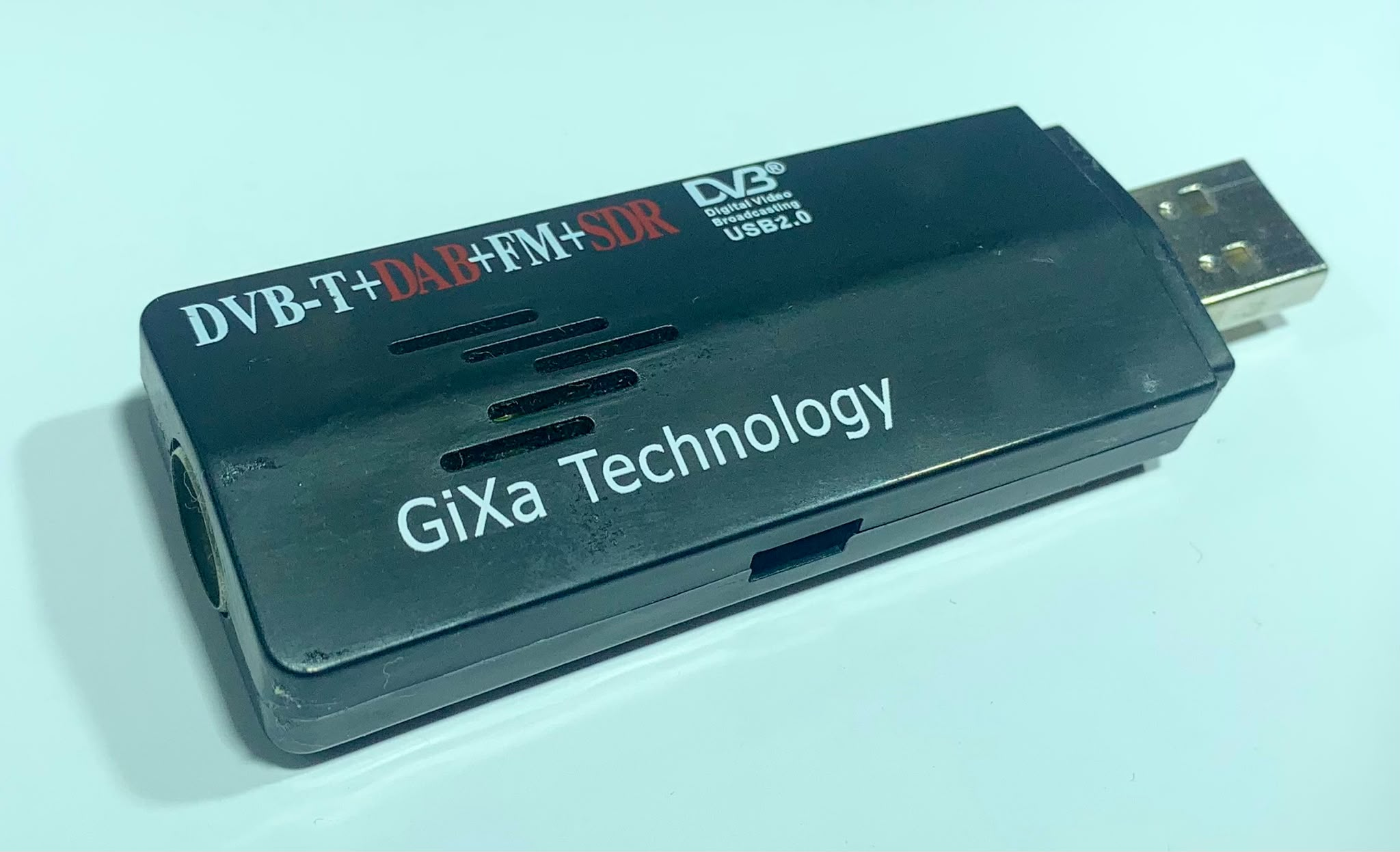
The best-known example is the RTL-SDR. It originated from inexpensive DVB-T USB TV dongles using the Realtek RTL2832U chip. These devices became popular as general-purpose SDR receivers because the chip can transfer raw I/Q samples to the host computer. Together with open-source drivers from the Osmocom project, this turned a mass-market TV receiver into an extremely low-cost radio scanner and SDR platform.
Technically, the RTL-SDR is not a high-performance receiver. Most versions have limited dynamic range, modest frequency stability and only basic front-end filtering. Historically, however, it is very important because it made SDR reception accessible to almost anyone. With a simple USB dongle and suitable software, users could suddenly receive and analyse FM broadcast, airband, ADS-B, AIS, weather satellites, radiosondes, DAB experiments and many other signals [26, 27].
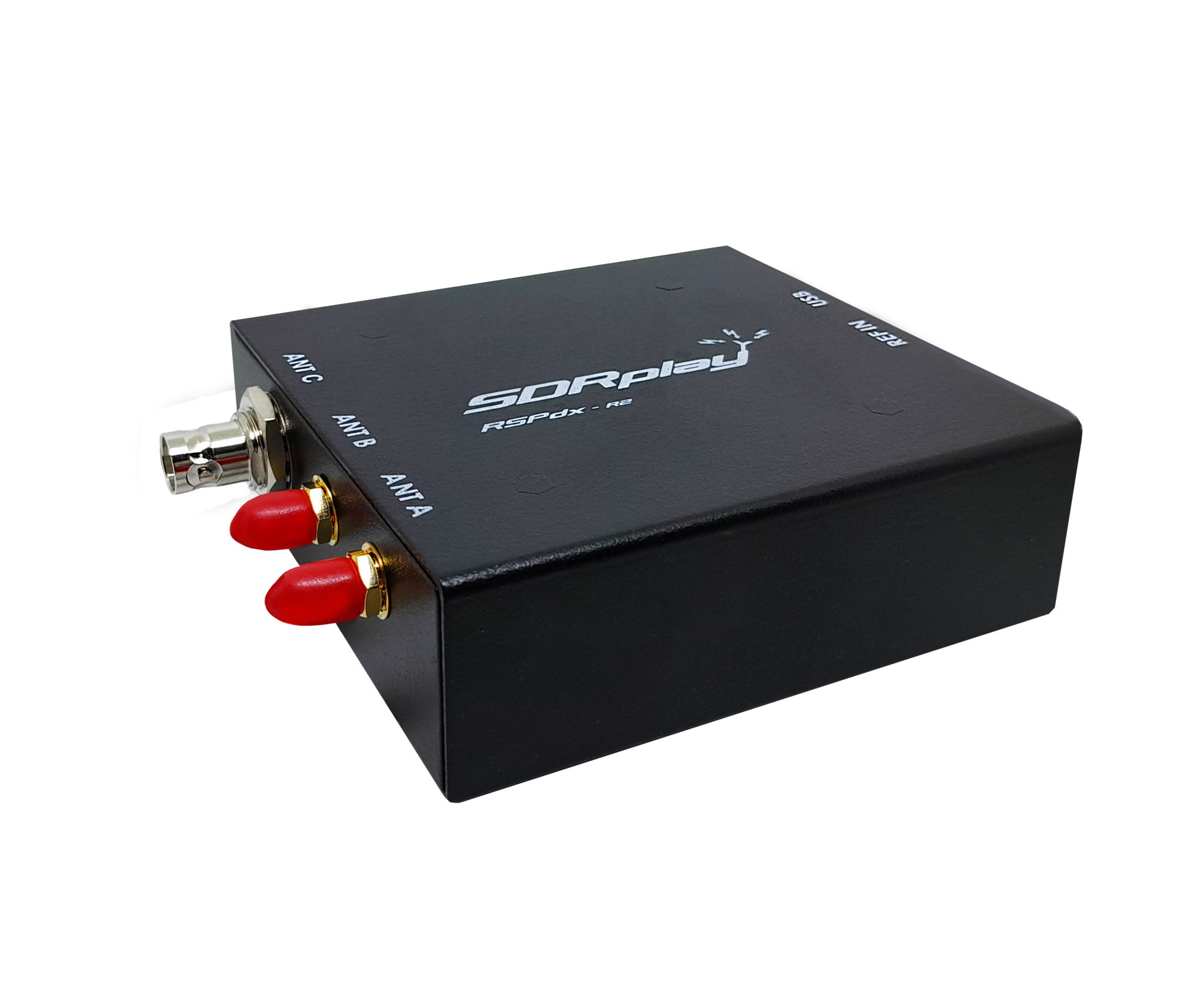
A more capable example of this general external-USB-SDR class is the SDRplay RSPdx. It is still a computer-controlled SDR receiver, but compared with a simple RTL-SDR dongle it offers better dynamic range, more front-end filtering and more flexible antenna inputs. SDRplay describes the RSPdx as a 14-bit wideband SDR covering 1 kHz to 2 GHz, with up to 10 MHz of visible spectrum and three antenna ports [28]. Devices such as the RSPdx illustrate the middle ground between very low-cost tuner SDRs and high-end direct-sampling or RFSoC systems.
Direct-sampling SDR
In direct-sampling receivers, especially for HF, the antenna signal is digitised very early in the signal chain, usually after protection circuits, attenuators and band-pass filtering. Digital oscillators, mixers, filters and decimators then extract the wanted channel.
Well-known examples of direct-sampling SDRs include the Icom IC-7300 and IC-7610, the FlexRadio FLEX-6000 series, the Elecraft K4 and receivers such as the Microtelecom Perseus. In these receivers, the RF signal is processed digitally in an FPGA or DSP chain very soon after the antenna input. The Icom IC-7300 is a particularly important example because it brought RF direct sampling into a relatively affordable mainstream amateur radio transceiver.
Direct sampling does not mean that the analogue frontend has disappeared. On the contrary, input filtering, protection, attenuators, preamplifiers and clock quality are still decisive. A direct-sampling receiver can have excellent performance, but only if the ADC is not overloaded by strong unwanted signals.
Direct RF sampling and RFSoC platforms
Modern high-speed ADCs can digitise increasingly wide RF bandwidths directly. This reduces or eliminates some analogue frequency-conversion stages. Texas Instruments describes direct RF sampling as digitising a large portion of RF spectrum directly and passing it to a signal processor [24]. AMD/Xilinx RFSoC devices take this idea further by integrating RF data converters, FPGA fabric and processor resources on one device [25].
RFSoC platforms such as AMD/Xilinx ZCU111, ZCU208 or ZCU216 are not typical broadcast or amateur-radio receivers. They are flexible wideband radio development systems for research, test equipment, radar, 5G, instrumentation and advanced SDR development. Their price and complexity put them far outside the usual hobby receiver world.
A somewhat more accessible example is the Real Digital RFSoC 4x2 board [29]. It is based on a Zynq UltraScale+ RFSoC device and provides multiple multi-gigasample ADC and DAC channels on one board. Together with the RFSoC-PYNQ project, it can be used from a Python/PYNQ environment and even includes ready-made examples such as a spectrum analyser. However, it is still mainly intended for universities and research institutes, not as a consumer or ordinary hobby SDR.
This makes RFSoC a useful example of where receiver architecture is heading: analogue frequency conversion is reduced, while sampling, digital downconversion, filtering and protocol processing move into FPGA and software. But it is not yet a direct replacement for practical hobby SDRs such as RTL-SDR, SDRplay, HackRF, ADALM-Pluto or conventional direct-sampling amateur transceivers.
Advantages and limits
The advantages of SDR architectures are significant:
- one receiver can support many modulation methods
- spectrum can be displayed and recorded
- several channels can be extracted from one wide digital stream
- software updates can add new modes
- reception, measurement and analysis begin to merge
However, physics does not disappear. An SDR is only as good as its analogue frontend. Strong out-of-band signals can overload the ADC. Quantisation noise, clock jitter, aliasing products and limited dynamic range set real limits.
For an ideal ADC, the theoretical signal-to-noise ratio is approximately:
SNRADC ≈ 6.02 N + 1.76 dB
where N is the number of bits. In practice, the effective number of bits, spurious-free dynamic range, clock purity and overload behaviour are more important than the nominal ADC resolution.
Clock jitter becomes especially critical at high input frequencies:
SNRjitter = −20 log10(2π fin σt)
Here, σₜ is the RMS timing jitter of the ADC sampling clock. It describes the small random timing uncertainty of the sampling instant. The higher the input frequency, the more this timing uncertainty is converted into amplitude noise. This is why high-performance SDRs depend not only on software, but also on careful analogue design, good filtering, clean clocks and a suitable antenna system.
10. DAB and DAB+: digital broadcasting as a receiver system
DAB is not simply “digital FM”. It is a completely different broadcasting system. It does not transmit one programme per RF channel. Instead, it transmits an ensemble or multiplex containing several audio programmes and data services. ETSI EN 300 401 defines DAB as a system for high-quality digital audio, video and data services for mobile, portable and fixed reception in VHF frequency bands [30].
Technically, DAB is based on COFDM. Many narrow carriers are transmitted in parallel. Each carrier has a relatively low symbol rate, which makes the system more robust against multipath propagation. The guard interval is essential: echoes arriving within this interval do not immediately destroy the OFDM symbol. This allows single-frequency networks, where several transmitters radiate the same multiplex on the same frequency.
A DAB receiver must therefore perform much more processing than an FM receiver:
- select the RF channel
- detect the OFDM symbol timing
- correct frequency offset
- synchronise the carriers
- decode the Fast Information Channel
- find the wanted service inside the multiplex
- perform deinterleaving and error correction
- reconstruct audio frames
- decode the audio codec
DAB+ is the modernised version. The major difference is the audio coding and additional error protection. ETSI TS 102 563 defines the use of HE-AAC v2 audio coding for DAB+ and describes the required audio transport and decoder requirements [31]. From the receiver’s point of view, DAB+ is not only a radio demodulator, but a complete digital communications decoder.
11. DRM, HD Radio and hybrid broadcast systems
In addition to DAB/DAB+, several other digital broadcast systems exist.
DRM / Digital Radio Mondiale
DRM was developed for digital broadcasting in existing broadcast bands, especially longwave, medium wave and shortwave, but also for VHF as DRM+. The system uses variable OFDM and coding parameters so that robustness and bitrate can be adapted to propagation conditions. The DRM organisation describes variable OFDM and coding parameters as a way to select the best compromise between transmit power, robustness and data capacity [32]. For shortwave, this is important because fading, multipath propagation and Doppler effects can be severe.
HD Radio / NRSC-5
In North America, HD Radio is standardised as NRSC-5. It is an in-band on-channel system. Digital sidebands are transmitted around the existing AM or FM signal. A station can transmit a main programme service, supplemental programme services and advanced data services [33]. A receiver must therefore handle both analogue and digital components and may have to blend or switch between them.
Hybrid Radio / RadioDNS
A modern car radio is increasingly no longer a pure RF receiver. It combines FM, DAB, DAB+, HD Radio or DRM with IP services. RadioDNS describes hybrid radio as a combination of broadcast radio and internet connectivity. The broadcast signal remains the robust and scalable audio path, while logos, metadata, programme information and sometimes alternative streams are delivered over IP [34].
The receiver is therefore becoming a hybrid broadcast/IP terminal.
12. DMR and digital voice receivers
DMR stands for Digital Mobile Radio. It is not a broadcast system but a digital professional mobile radio standard. Nevertheless, it is highly relevant to modern receiver technology because it shows how far the term “radio receiver” has moved away from simple audio demodulation.
DMR uses two-slot TDMA in a 12.5 kHz channel. The DMR Association explains that one 12.5 kHz channel can support two simultaneous and independent calls by dividing the channel into two alternating time slots [35].
A DMR receiver must:
- demodulate a 4FSK signal
- recover symbol timing
- correct frequency error
- recognise the time-slot structure
- decode colour code, talkgroup and station IDs
- apply forward error correction
- decode the vocoder bitstream
- reconstruct speech
- in trunked systems, interpret control-channel information
Internally, a DMR receiver is therefore much closer to a small digital communications terminal than to a classic FM receiver.
Similar developments exist in other digital voice systems:
- TETRA uses four TDMA time slots in a 25 kHz RF channel [36].
- P25 is used mainly in public safety radio systems, especially in North America.
- NXDN and dPMR use narrowband FDMA concepts.
- D-STAR is a digital amateur radio voice and data standard published by the Japan Amateur Radio League [37].
- System Fusion, M17 and other amateur systems follow similar digital-radio ideas with different technical and licensing philosophies.
Digital voice systems also change the user’s perception of reception quality. Analogue FM becomes gradually noisier as the signal weakens. Digital voice remains clean until synchronisation and error correction can no longer cope. Then it produces artefacts, dropouts or complete silence. This “cliff effect” is characteristic of many digital systems.
13. Modern receivers are protocol machines
In a classic analogue radio, most of the work was finished after demodulation. In modern receivers, demodulation is often only the beginning.
A present-day digital receiver may contain the following layers:
- RF frontend
- ADC and digital frontend
- synchronisation
- channel estimation
- equalisation
- demodulation
- deinterleaving
- error correction
- framing
- protocol decoding
- codec processing
- user interface or network interface
This applies to DAB, DRM, DMR, TETRA and P25, but also to WLAN, LTE and 5G.
In 5G NR, the receiver no longer receives “a station” in the classical sense. It receives a time-frequency resource grid. It must estimate the radio channel, equalise multipath propagation, process MIMO layers, demap QAM symbols, decode LDPC or polar codes, handle HARQ processes and finally deliver IP data.
From a radio-history perspective, however, the line is continuous. The receiver still extracts information from a weak electromagnetic signal. Only the internal implementation has changed from a tuned detector to a highly integrated signal-processing computer.
14. Spectrum display, waterfall and recording: a new way of looking at radio
A traditional radio shows a frequency and produces sound. An SDR shows a spectrum. This changes how radio is used and understood.
A waterfall display is more than a visual gimmick. It is a time-frequency measurement instrument. It can reveal:
- FM carriers and RDS subcarriers
- DAB blocks as wide OFDM signals
- digital voice channels
- ADS-B at 1090 MHz
- AIS around 162 MHz
- weather radiosondes
- satellite telemetry
- shortwave fading
- local interference sources
- switching power supply harmonics
An SDR can also record an entire I/Q bandwidth. This is technically important. A signal can be analysed later using different filters, demodulators or software. Reception becomes reproducible. What was once a single listening moment becomes a data set.
15. Limits of modern receivers
Even with digital processing, some limits remain unchanged.
Antenna and location
No ADC can fully compensate for a poor antenna. Antenna gain, polarisation, grounding, common-mode currents, local noise and site quality remain decisive.
Preselection
A wideband SDR without preselection can be overloaded by strong FM, DAB, mobile radio or broadcast transmitters. The wanted frequency may look clean, while the ADC is already being driven into compression by out-of-band signals.
Dynamic range
An 8-bit SDR can be extremely useful, but its usable dynamic range is limited. Higher-quality receivers use 12, 14 or 16 bits, but frontend design, clock quality and filtering still determine real-world performance.
Clock quality
For narrow digital signals, satellite reception, coherent multi-channel receivers and measurement applications, the frequency reference is critical. TCXO, OCXO or GPSDO references may be required.
Software complexity
An analogue receiver can largely be understood from its schematic. A modern receiver also requires firmware, FPGA design, drivers, DSP algorithms, codecs and protocol knowledge. The failure modes shift: not only coil alignment and bad solder joints matter, but also buffer overruns, USB latency, driver problems and numerical instability.
16. Artificial intelligence and future receivers
Artificial intelligence will probably not replace the antenna, the low-noise amplifier or the analogue frontend. Physics remains. AI is more likely to appear in areas where classical algorithms are complex, adaptive or dependent on changing conditions.
Possible uses include:
- automatic modulation recognition
- interference classification
- adaptive filtering
- detection of illegal or faulty transmissions
- spectrum monitoring
- automatic station identification
- intelligent squelch systems
- neural channel equalisation
- MIMO detection
- improved synchronisation and demapping
Current research already demonstrates neural receivers for 5G NR MU-MIMO scenarios. In such systems, channel estimation, equalisation and demapping can be performed jointly by a neural network [38]. For broadcast and amateur radio receivers, the short-term impact will probably be more practical: better noise reduction, automatic mode detection, transcription, signal classification and spectrum search.
A careful prediction would be: AI will not replace the radio receiver, but it will optimise parts of the digital baseband chain. The receiver of the future may combine a good analogue frontend, direct digitisation, classical DSP and learning algorithms.
17. Conclusion: the form changes, the task remains
From the crystal detector to the RFSoC, almost everything has changed: components, stability, filters, modulation methods, user interfaces and protocols. But the fundamental task remains the same: information must be recovered from a weak electromagnetic signal.
The historical development can be seen as a gradual shift of receiver functions:
- detector era: demodulation by nonlinearity
- vacuum tube era: amplification, oscillation and mixing
- superhet era: fixed intermediate frequency and high-quality filters
- transistor era: miniaturisation and battery operation
- IC era: integration, PLL synthesis and digital control
- DSP era: digital filters and demodulators
- SDR era: I/Q data and software-defined receiver structures
- present day: RF sampling, OFDM, FEC, protocols, IP integration and AI assistance
The old radio was a tuned electrical apparatus. The modern radio is a reconfigurable signal-processing system. But even the most advanced SDR remains a radio receiver in one essential respect: before the software comes the antenna.
Glossary of abbreviations and technical terms
ADC – Analogue-to-Digital Converter
Converts an analogue voltage signal into digital samples. In SDR receivers, the ADC is one of the most critical components because its resolution, sampling rate, clock quality and overload behaviour strongly influence receiver performance.
AGC – Automatic Gain Control
A control loop that automatically adjusts receiver gain depending on signal strength. It prevents overload on strong signals and improves usability on weak signals.
AM – Amplitude Modulation
A modulation method where the amplitude of the carrier is varied according to the audio or information signal. AM was the classic modulation method for longwave, medium wave and shortwave broadcasting.
AVC – Automatic Volume Control
Older term, often used in broadcast receivers, for automatic gain control. In many contexts AVC and AGC describe essentially the same receiver function.
BFO – Beat Frequency Oscillator
An oscillator used in a receiver to make CW or SSB signals audible. It provides a local carrier that is mixed with the received signal.
COFDM – Coded Orthogonal Frequency Division Multiplexing
A digital modulation method using many closely spaced orthogonal carriers together with error correction. DAB and DAB+ use COFDM.
CW – Continuous Wave
A radio mode mainly used for Morse code. The transmitter sends an unmodulated carrier that is switched on and off. The receiver needs a BFO or product detector to make it audible.
DAB – Digital Audio Broadcasting
A digital radio broadcasting system using OFDM/COFDM. Several audio programmes and data services are transmitted together in one multiplex.
DAB+ – Digital Audio Broadcasting Plus
An improved version of DAB using a more efficient audio codec, HE-AAC v2, and additional error protection. DAB+ is the dominant form of digital terrestrial radio in many countries.
DAC – Digital-to-Analogue Converter
Converts digital samples back into an analogue signal. In receivers it may be used for audio output; in transmitters and transceivers it is used to generate RF or IF signals.
dBm – Decibels referenced to 1 milliwatt
A logarithmic power unit. 0 dBm corresponds to 1 mW. Very weak radio signals are often expressed in negative dBm values.
DMR – Digital Mobile Radio
A digital voice and data radio standard mainly used for professional mobile radio and also by radio amateurs. DMR uses two-slot TDMA in a 12.5 kHz channel.
DSP – Digital Signal Processing / Digital Signal Processor
Digital processing of signals using algorithms. In receivers, DSP can implement filters, demodulators, AGC, noise reduction, spectrum displays and many other functions.
DRM – Digital Radio Mondiale
A digital broadcasting system intended for longwave, medium wave, shortwave and VHF broadcasting. It uses OFDM and efficient audio coding.
ENOB – Effective Number of Bits
A practical measure of ADC performance. It describes the real usable resolution of an ADC, including noise and distortion effects.
FEC – Forward Error Correction
A method of adding redundant information to a transmitted signal so that the receiver can correct transmission errors without requesting retransmission.
FM – Frequency Modulation
A modulation method where the instantaneous frequency of the carrier is varied according to the audio or information signal. FM is used for VHF broadcasting and many voice communication systems.
FPGA – Field Programmable Gate Array
A programmable logic device often used for high-speed digital signal processing. Many modern SDRs use FPGAs for digital downconversion, filtering and data handling.
GPSDO – GPS Disciplined Oscillator
A highly stable frequency reference disciplined by GPS. It is used when long-term frequency accuracy is important.
HD Radio – High Definition Radio / NRSC-5
A digital radio broadcasting system used mainly in North America. It transmits digital signals in or near the existing AM or FM broadcast channel.
HE-AAC – High Efficiency Advanced Audio Coding
An efficient audio codec used in several digital radio systems. DAB+ uses HE-AAC v2.
HF – High Frequency
The frequency range from 3 MHz to 30 MHz. In radio practice, this is commonly called shortwave.
IF – Intermediate Frequency
A fixed frequency used inside a superheterodyne receiver after mixing. Filtering and amplification are easier to optimise at a fixed IF than directly at the received RF frequency.
I/Q – In-phase and Quadrature components
The two components of a complex baseband signal. I and Q together contain amplitude and phase information and are fundamental to SDR and modern digital receivers.
IP2 / IP3 – Second- and Third-Order Intercept Point
Figures of merit describing receiver linearity and intermodulation performance. A high IP3 usually indicates good large-signal behaviour.
LDPC – Low-Density Parity-Check Code
A powerful error-correcting code used in modern digital communication systems, including 5G NR.
LF – Low Frequency
The frequency range from 30 kHz to 300 kHz. This includes longwave broadcasting in some regions.
LO – Local Oscillator
An oscillator inside a receiver used for frequency conversion. In a superhet, the LO is mixed with the incoming RF signal to create the IF.
MIMO – Multiple Input Multiple Output
A radio technique using multiple antennas at the transmitter and receiver to improve data rate, reliability or both. MIMO is used in WLAN, LTE and 5G systems.
MF – Medium Frequency
The frequency range from 300 kHz to 3 MHz. It includes the traditional medium-wave AM broadcast band.
MPX – Multiplex signal
In FM stereo broadcasting, the MPX signal contains mono audio, stereo difference information, pilot tone and often RDS data.
NCO – Numerically Controlled Oscillator
A digitally generated oscillator used in SDRs for mixing, tuning and frequency conversion in the digital domain.
NF – Noise Figure
A measure of how much noise a receiver or amplifier adds to the signal. A lower noise figure generally means better sensitivity.
NRSC-5 – National Radio Systems Committee Standard 5
The technical standard behind HD Radio in-band/on-channel digital broadcasting.
OCXO – Oven-Controlled Crystal Oscillator
A highly stable crystal oscillator kept at a constant temperature. It provides better stability than a normal crystal oscillator or TCXO.
OFDM – Orthogonal Frequency Division Multiplexing
A digital modulation method that divides the data stream over many closely spaced orthogonal subcarriers. OFDM is used in DAB, DRM, WLAN, LTE and 5G.
PLL – Phase-Locked Loop
A control loop that locks an oscillator to a reference frequency. PLLs are widely used in synthesised receivers for stable and accurate tuning.
PSK – Phase Shift Keying
A digital modulation method where information is represented by changes in carrier phase.
QAM – Quadrature Amplitude Modulation
A digital modulation method where both amplitude and phase are varied. QAM is widely used in modern communication systems.
RF – Radio Frequency
The high-frequency electrical signal received from the antenna or processed before conversion to IF or baseband.
RFSoC – Radio Frequency System on Chip
An integrated device that combines RF data converters, digital processing and programmable logic. RFSoCs are used in advanced SDR and communication systems.
RDS – Radio Data System
A digital data service transmitted on a 57 kHz subcarrier in FM broadcasting. It carries information such as station name, programme type, alternative frequencies and radiotext.
SDR – Software Defined Radio
A radio architecture where many receiver or transmitter functions are implemented in software instead of fixed analogue hardware. SDR usually works with digital I/Q samples.
SFDR – Spurious-Free Dynamic Range
The ratio between the wanted signal and the largest unwanted spur in a receiver or ADC system. It is an important practical dynamic range parameter.
SNR – Signal-to-Noise Ratio
The ratio between wanted signal power and noise power. Higher SNR usually means better reception or lower error rate.
SSB – Single Sideband
A form of amplitude modulation where the carrier and one sideband are suppressed. SSB is very bandwidth- and power-efficient and is widely used in voice communication on HF.
TCXO – Temperature-Compensated Crystal Oscillator
A crystal oscillator with temperature compensation. It is more stable than a simple crystal oscillator but usually less stable than an OCXO or GPSDO.
TDMA – Time Division Multiple Access
A multiple-access method where users share the same RF channel by transmitting in different time slots. DMR and TETRA use TDMA.
TETRA – Terrestrial Trunked Radio
A digital trunked radio standard used mainly by public safety, transport and industrial users. It uses four TDMA time slots in a 25 kHz channel.
TRF – Tuned Radio Frequency receiver
An early receiver architecture in which all RF amplification and filtering take place directly at the received frequency.
UHF – Ultra High Frequency
The frequency range from 300 MHz to 3 GHz. It includes many communication, broadcast, satellite and radar services.
VFO – Variable Frequency Oscillator
A tunable oscillator used in older receivers and transmitters. In many modern designs it has been replaced by PLL or DDS synthesizers.
VHF – Very High Frequency
The frequency range from 30 MHz to 300 MHz. It includes FM broadcasting, DAB in Band III, airband, marine radio and many land mobile services.
Vocoder – Voice Coder
A codec that compresses speech into a low-bitrate digital data stream and reconstructs speech at the receiver. Digital voice systems such as DMR use vocoders.
xHE-AAC – Extended High Efficiency Advanced Audio Coding
A very efficient modern audio codec used in some digital broadcasting and streaming systems, including DRM applications.
Sources and further reading
[1] NobelPrize.org – The Nobel Prize in Physics 1909, Marconi and Braun
https://www.nobelprize.org/prizes/physics/1909/summary/
[2] History of Information – John Ambrose Fleming Invents the Vacuum Tube, Beginning Electronics
https://historyofinformation.com/detail.php?id=561
[3] Britannica – Audion summary
https://www.britannica.com/summary/Audion
[4] Austrian Centre for Digital Humanities and Cultural Heritage – Robert von Lieben
https://www.biographien.ac.at/oebl/oebl_L/Lieben_Robert_1878_1913.xml
[5] Karl Skowronnek, “Zur Entwicklung der Elektronenverstärker-Röhre (Lieben-Röhre)” [On the development of the electron amplifier tube / Lieben tube], in Archiv für Geschichte der Mathematik, der Naturwissenschaften und der Technik, Vol. 13, New Series IV (1930/31), edited by Julius Schuster. Berlin: Verlag von F. C. W. Vogel, 1931.
[6] Engineering and Technology History Wiki – Edwin H. Armstrong
https://ethw.org/Edwin_H._Armstrong
[7] Engineering and Technology History Wiki – Alexander Meissner
https://ethw.org/Alexander_Meissner
[8] Espacenet – Alexander Meißner, DE291604C, “Einrichtung zur Erzeugung elektrischer Schwingungen”
https://worldwide.espacenet.com/patent/search/family/000546471/publication/DE291604C?q=pn%3DDE291604C
[9] Radiomuseum.org – VE301 Dyn W Volksempfänger, technical data
https://www.radiomuseum.org/r/gemeinsch_ve301dyn_w.html
[10] United States Holocaust Memorial Museum – German Radio: The People’s Receiver
https://exhibitions.ushmm.org/propaganda/german-radio-the-peoples-receiver
[11] Engineering and Technology History Wiki – Superheterodyne Receiver
https://ethw.org/Superheterodyne_Receiver
[12] IEEE Communications Society – Superheterodyne Patents and Applications; Armstrong and Schottky
https://www.comsoc.org/node/18901
[13] IEEE Communications Society – Superheterodyne Radio Patented; Lucien Lévy’s French patents
https://www.comsoc.org/node/18896
[14] AEG / Dr. Lübeck – Entwicklungstendenzen des Rundfunks, 1940; table XXX: “Anteil der Superhet- und Geradeausempfänger am Inlands- und Auslandsabsatz”
[15] ETSI ETS 300 384 – VHF FM sound broadcasting transmitters; FM multiplex, pilot tone and RDS subcarrier
https://www.etsi.org/deliver/etsi_i_ets/300300_300399/300384/01_60/ets_300384e01p.pdf
[16] Computer History Museum – 1947: Invention of the Point-Contact Transistor
https://www.computerhistory.org/siliconengine/invention-of-the-point-contact-transistor/
[17] NXP / Philips TEA5767 datasheet – Single-chip electronically tuned FM stereo radio
https://cdn.sparkfun.com/assets/4/5/f/a/d/TEA5767.pdf
[18] NXP application note – Low-voltage FM stereo radio with TEA5767/68
https://www.rockbox.org/wiki/pub/Main/DataSheets/application_note_tea5767-8.pdf
[19] Skyworks / Silicon Labs Si4732-A10 short datasheet – Broadcast AM/FM/SW/LW/RDS radio receiver
https://www.skyworksinc.com/-/media/Skyworks/SL/documents/public/data-shorts/Si4732-A10-short.pdf
[20] PU2CLR Si4735 Arduino Library – Si47xx receiver control and SSB patch support
https://github.com/pu2clr/SI4735
[21] PU2CLR Si4735 Wiki – Notes on SSB patch support for Si47xx devices
https://github.com/pu2clr/SI4735/wiki
[22] IEEE Communications Society – Software Radio / Joseph Mitola
https://www.comsoc.org/node/19896
[23] GNU Radio – About GNU Radio
https://www.gnuradio.org/about/
[24] Texas Instruments – Direct RF Conversion: From Vision to Reality
https://www.ti.com/lit/slyy068
[25] AMD/Xilinx – An Adaptable Direct RF Sampling Solution
https://www.amd.com/content/dam/amd/en/documents/solutions/direct-rf-sampling-solution-white-paper.pdf
[26] Osmocom – rtl-sdr project; Realtek RTL2832U DVB-T dongles as low-cost SDR receivers using raw I/Q samples
https://osmocom.org/projects/rtl-sdr/wiki
[27] RTL-SDR.com – About RTL-SDR; overview of RTL-SDR as a low-cost USB SDR receiver
https://www.rtl-sdr.com/about-rtl-sdr/
[28] SDRplay – RSPdx wideband 14-bit SDR receiver
https://www.sdrplay.com/rspdx/
[29] RFSoC-PYNQ – Real Digital RFSoC 4x2 overview
https://www.rfsoc-pynq.io/rfsoc_4x2_overview.html
[30] ETSI EN 300 401 – Radio Broadcasting Systems; Digital Audio Broadcasting
https://www.etsi.org/deliver/etsi_en/300400_300499/300401/02.01.01_60/en_300401v020101p.pdf
[31] ETSI TS 102 563 – DAB+ audio coding using MPEG HE-AAC v2
https://www.etsi.org/deliver/etsi_ts/102500_102599/102563/02.01.01_60/ts_102563v020101p.pdf
[32] Digital Radio Mondiale – DRM Technology
https://www.drm.org/about-drm/drm-technology/
[33] NRSC-5-D – In-band/on-channel Digital Radio Broadcasting Standard
https://www.nrscstandards.org/standards-and-guidelines/documents/standards/nrsc-5-d/nrsc-5-d.pdf
[34] RadioDNS – Hybrid Radio Standards
https://radiodns.org/
[35] DMR Association – Digital Mobile Radio standard overview
https://www.dmrassociation.org/
[36] TCCA – TETRA ETSI standards and technical overview
https://tcca.info/tetra/for-tetra-specialist/etsi-standards/
[37] JARL – Digitalization Technology Standard for Amateur Radio / D-STAR
https://www.jarl.org/English/7_dstar/STD6_0_E.pdf
[38] NVIDIA Research – A Neural Receiver for 5G NR Multi-user MIMO
https://research.nvidia.com/publication/2023-12_neural-receiver-5g-nr-multi-user-mimo