From Workshop Sheet to Netlist
The Schematic Diagram as a Technical Language
Anyone restoring a historic radio receiver does not only read components, wires and tube designations. They also read a technical language. That language is the schematic diagram. To the trained eye, it shows more than the electrical connection of individual components: it reveals signal paths, the state of development, manufacturing philosophy, repair possibilities and sometimes also the economy or ingenuity of a manufacturer.
The schematic diagram is not a natural or self-evident form of representation. It is the result of a long development. Between an early wiring drawing, a circuit diagram in a radio service manual, a page from the Empfänger-Vade-Mecum and a modern CAD schematic lie not only decades, but also different ideas about what a schematic diagram is meant to do. In earlier times it was mainly a tool for design, production and repair. Later it was distributed through large circuit diagram collections. Today it is also part of a digital development process: from the drawn circuit come netlists, design rules, printed circuit boards, bills of materials, simulations and manufacturing data.
The diagram remains — but its form and its function have changed.
From Apparatus Drawing to Functional Representation
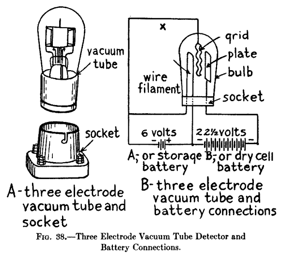
In the early days of electrical documentation, representation was often still descriptive and visual. A device was drawn in such a way that its construction or wiring could be recognised. For simple circuits this was sufficient: battery, switch, coil, wire, contact. Such drawings answered very practical questions: Where is the part? Which terminal is connected to which wire? How can the apparatus be assembled or repaired?
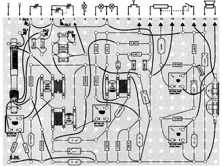
This type of representation did not disappear completely. It survived wherever the main purpose was not formal documentation, but explanation, construction and orientation. In educational material, experimenter’s books and later electronics kits, the learner often needed to see not only the electrical function, but also the physical arrangement: where the coil sits, where the capacitor is connected, which terminal of the battery goes to which contact. In this sense, early apparatus drawings, wiring diagrams and later component-location drawings belong to the same family of representations. They answer a different question from the abstract schematic. The schematic asks: “How does the circuit work electrically?” The layout or component-location drawing asks: “Where is it, and how do I build or find it?”
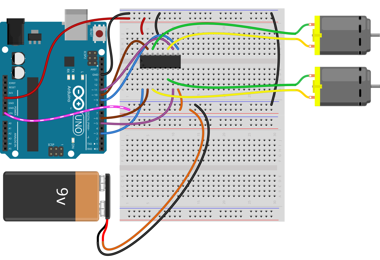
This tradition can still be seen much later in electronics experiment kits, for example in Philips educational sets, where the circuit and the physical board arrangement were often presented side by side [2]. It also continues in modern maker tools such as Fritzing, whose breadboard view deliberately shows a circuit in a form close to the way it is assembled on the workbench [3]. In professional electronics, such pictorial representation is usually only an auxiliary view. In education, prototyping and troubleshooting, however, it remains useful because it connects the abstract circuit with the physical object.
The more complex electrical devices became, however, the less a purely descriptive drawing could achieve. This step is particularly clear in the case of the radio receiver. Mechanically, a radio is a box with chassis, dial, tuning capacitor, coils, tube sockets, loudspeaker, power transformer and many wires. Electrically, however, it is a sequence of functional groups: input circuit, oscillator, mixer stage, intermediate-frequency amplifier, detector, audio amplifier and power supply. The schematic diagram therefore detaches itself from the physical arrangement and instead shows the electrical function.
This abstraction is the decisive point. A capacitor is not drawn as it physically looks inside the set. A tube is not placed where its socket sits on the chassis. A coil is not represented according to its actual winding form. The diagram arranges components in such a way that their electrical relationship becomes visible. In this way, the schematic diagram becomes a language.
Like any language, this language developed its own signs, habits and regional differences. Resistors, capacitors, coils, tubes, switches, ground points, shields and transformers became graphical building blocks from which complex statements could be formed. An experienced technician therefore does not read a good schematic component by component, but recognises functional blocks and typical circuit arrangements.
This readability is especially important in tube radios. At first glance, a superheterodyne receiver may appear confusing: multi-section switches, coil assemblies, feedback paths, alignment points, band switching, negative feedback, tone control, hum suppression in the power supply. In the schematic diagram, this complexity can be organised. It does not show what the device looks like, but how it works electrically.
Standardisation and Readability
A technical language works better when its symbols are understood. In the case of electrical schematic diagrams, this was by no means self-evident from the beginning. Many forms of representation first arose from workshop practice, manufacturer habits and national conventions. A resistor, a capacitor, a coil or a tube were generally recognisable components, but their graphical representation was not always uniform. Ground, earth, chassis, shielding and switch positions were also not always treated consistently in older documents.
In historical radio receivers, one therefore often finds a mixture of standardisation, habit and publishing style. European and American symbols sometimes differ. Tubes may be drawn in different ways. Waveband switches are sometimes shown in great detail, sometimes in a highly simplified form. In multi-band receivers with several switch wafers, coil sets and alignment points, the way in which these elements are represented often determines whether a diagram is easy to read or not.
Later standardisation attempted to reduce such differences. In the United States, IEEE/ANSI 315-1975 is an important example, a standard for graphic symbols and reference designations in electrical and electronic diagrams [4]. What is interesting is not only the collection of symbols itself, but also the idea that the connection points of symbols should lie on a modular grid. The schematic diagram is thus systematised not only in content, but also in its graphical construction.
Internationally, IEC 60617 plays a comparable role [5]. This standard covers graphical symbols for electrotechnical diagrams and today exists not only as a printed body of standards, but as a database. This is a remarkable step: the standard itself follows the transition from printed technical drawing to a digital, searchable collection of symbols.
For the radio repair technician of the classic period, however, formal standardisation was only one side of the matter. Practical readability was just as important. A circuit diagram could be formally correct and still be confusing. A good radio schematic had to make functional groups recognisable: input circuit, oscillator, mixer stage, IF amplifier, detector, audio section and power supply. Additional information such as tube voltages, intermediate frequency, alignment points, switch positions and component values was particularly useful. The technical language therefore consisted not only of symbols, but also of the way in which they were arranged and annotated.
The Schematic Diagram in the Radio Workshop
For the workshop, the schematic diagram was not decoration, but a working tool. It had to be quickly readable and provide answers to practical questions: Which tube is used in which stage? Which voltages are to be expected? Which winding belongs to which band? Where are the alignment points? How is the waveband switch wired? Which component values are critical?
A complete set of service information therefore often consisted of more than just the circuit diagram itself. Particularly useful were additional data: tube line-up, electrode voltages, alignment instructions, intermediate frequency, dial cord diagram, component layout, dial drive, spare parts list or notes on equipment variants.
The quality of such documentation varied considerably. Manufacturer service sheets could be very good, but they were not always available. Some diagrams were clear, others were difficult to read because of complex multi-section switches or cramped layout. Printed collections introduced further problems: redrawing, reduction in size, printing errors, missing variants or unclear source information.
Nevertheless, the schematic diagram became the central tool of repair practice. Without a diagram, the technician had to measure, trace, compare and rely on experience. With a diagram, work could proceed more systematically. The schematic was therefore not only technical documentation, but also a means of saving time.
Circuit Diagram Collections as a Means of Distribution
With the spread of radio technology, a further need arose: not only individual manufacturer documents were required, but large collections. A radio workshop could not keep original service information for every model, every manufacturer and every variant. Circuit diagram collections were therefore an obvious answer.
In Germany, the Empfänger-Vade-Mecum is a particularly interesting example of post-war workshop literature. Published by Regelien in Berlin and associated with W. A. Schenk and later additions, it appeared in the immediate post-war years, in a period when radio repair was a practical necessity rather than a collector’s activity. A contemporary review in Funkschau in 1946 described it as a collection of circuit diagrams of industrial receivers “for construction and repair” and noted that it had already become a familiar term in radio workshops [6]. The same review praised the uniform drawing style, the use of standardised symbols, component values and tube current and voltage data, and stated that the planned work would comprise 28 booklets with 2386 pages of circuit diagrams. Later notes describe earlier and post-war Regelien / W. A. Schenk Empfänger Vade-Mecum editions, including bound volumes, separate booklets and alignment material [7].
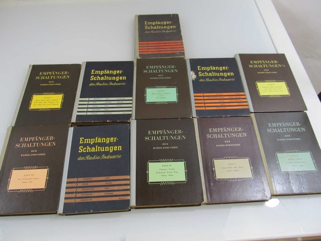
Rudolf Grabau’s survey of radio-technical literature from 1942 to 1948 places the Empfänger Vademecum even more clearly in the immediate post-war repair context: it was not a collector’s publication, but a practical response to the shortage of service information and the need to keep existing receivers in operation [8]. Grabau also discusses the later Empfänger-Schaltungen der Radio-Industrie by Heinz Lange and Heinz K. Nowisch. These volumes represented another form of collection: extensive, book-based, systematic and intended as a reference work. The Austrian volumes are of particular value today for the study of Austrian radio technology. They show that such collections were not only technical aids, but are now also sources for industrial and equipment history.
For Switzerland, the Thali schematic collection is an interesting counterpart [9]. Hans Thali’s H. Thali & Cie. had its roots in radio trade, construction and service work, not simply in publishing. According to a later biographical account, Thali recognised the lack of service schematics as a market gap and brought a collection of around 1500 circuit diagrams and parts lists for sets sold in Switzerland onto the market around 1942, distributed in twelve monthly deliveries. The same account describes how the schematic collection and a later technical dictionary gradually turned the firm from a radio dealer into a publisher and mail-order book business; by 1951 H. Thali & Cie. was also acting as Swiss representative of the German Franzis-Verlag [10]. In this sense, the Thali collection stood between commerce, repair and technical information.
These collections therefore had a double function. On the one hand, they were everyday tools. On the other hand, they distributed the technical language of the schematic diagram. They unified what was scattered across many manufacturer documents and made it manageable for workshops.
From Repair Tool to Historical Source
Today, collectors and restorers often use these old documents in a different way from their original purpose. A schematic diagram was initially a tool for repairing a device. Today it is also a historical source.
This calls for source criticism. A circuit diagram collection is not automatically identical with the original manufacturer documentation. Original service data may refer to a particular production series, and the correct issue sometimes has to be checked against the factory or serial number of the set. Circuit diagram collections, by contrast, often give few or no issue details and may contain simplified principle diagrams rather than full manufacturer service data. A diagram may also have been redrawn, reduced, shortened or assembled from several sources. Sometimes information on year of manufacture, variant, chassis number or export version is missing.
With historical radios, this can have practical consequences. A set on the workbench does not necessarily correspond exactly to the printed diagram. Component values may have been changed, production modifications may be missing, and repairs from earlier decades may have left their traces. The schematic is then not an absolute truth, but a starting point for investigation.
Despite these limitations, such collections are indispensable. In many cases, an incomplete or secondary circuit diagram is better than none at all. They also show which sets were considered important enough to document, which manufacturers were present and which circuit forms were widespread. They are therefore both repair aids and mirrors of technical culture [11].
From Drawn Diagram to Calculable Model
A significant turning point came with the possibility of not only drawing circuits, but also analysing them mathematically. Programs such as SPICE turned the circuit into a formal model that could be processed by a computer. In their 1973 Berkeley report, Laurence W. Nagel and D. O. Pederson described SPICE as a circuit simulation program combining nonlinear DC analysis, small-signal analysis and nonlinear transient analysis in a nodal analysis program [12]. With this, a new stage had been reached: the circuit was no longer only documentation for humans, but also input for computation [13].
This step fundamentally changed the role of the schematic diagram. In a classic radio diagram, the technician must infer the behaviour of the circuit from experience, measurement and understanding. In a simulated circuit, component models, nodes and connections are evaluated mathematically. This does not mean that simulation replaces practical experience. Models may be incomplete, parasitic effects may be missing, and component tolerances may be assumed incorrectly. But the basic idea is new: the circuit represented in the diagram can be investigated virtually before it is built.
For historical radio receivers, SPICE is not the natural starting point. Most tube radios were developed without such tools, and many repairs are better solved with a diagram, measuring instrument and experience than with simulation. Nevertheless, the idea is important for the history of the schematic diagram. Step by step, the diagram changes from a drawing into a formal description. What was once only read can now also be calculated.
The Modern CAD Schematic
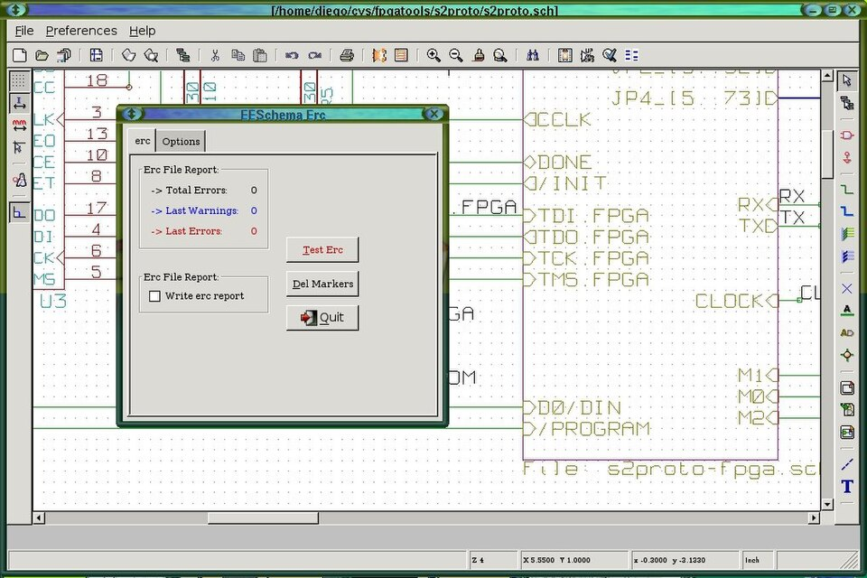
In today’s development environments such as Altium Designer, KiCad, OrCAD, EAGLE or comparable systems, the schematic diagram is no longer just a sheet of paper. It is part of an electronic design automation project. Modern EDA suites combine schematic capture with PCB layout, libraries, simulation, 3D representation and data export; KiCad, for example, describes itself explicitly as an EDA suite with schematic capture, integrated circuit simulation, PCB layout, 3D rendering and export functions [14].
The English term “schematic capture” describes this step quite precisely: the circuit is not simply drawn, but entered in a form that the CAD system can process further. Altium’s documentation describes the schematic stage as “capturing your design idea as a schematic” and treats component placement, connectivity, multi-sheet structures and reuse as part of this design-capture process [15].
A component in a modern schematic consists not only of a graphical symbol. It has pins, electrical properties, a reference designator, value, footprint, manufacturer data, ordering information and often additional parameters. Altium’s documentation states this explicitly: when a component is placed in a schematic, its schematic symbol is linked to other models, such as a PCB footprint and simulation model, and equipped with a list of parameters [15]. Similarly, KiCad’s documentation describes the association of schematic symbols with PCB footprints as a normal step before laying out the printed circuit board [16].
A wire is not merely a drawn line, but belongs to an electrical net. This net can be named, checked, carried across several schematic pages and later used in the PCB layout. Autodesk’s EAGLE documentation explains this in practical terms: schematic symbols are connected by nets, and intersecting nets require junctions when they are intended to share an electrical connection [17].
From the schematic, a netlist or comparable connectivity data is generated or maintained. It describes which pins are electrically connected to each other. OrCAD documentation describes the netlist as the means by which the schematic design, components and connections are communicated to PCB layout [18]. KiCad documentation similarly states that its Schematic Editor can export netlist files listing all electrical connections, although modern integrated workflows may also communicate directly between schematic and PCB editors [16]. For the human reader, the schematic remains the readable representation; for the machine, this connectivity data is the decisive structure. The schematic thus becomes an interface between human understanding and machine processing.
The CAD system can then perform electrical rule checks. In KiCad, the Electrical Rules Checker checks for schematic errors such as unconnected pins, unconnected hierarchical symbols, shorted outputs and other illegal connections [16]. OrCAD X Capture likewise offers schematic design rule checking before PCB layout, including rule setup for electrical, physical and simulation-related checks [19]. Such checks do not replace engineering judgement, but they change the workflow. Many errors that previously became apparent only in the prototype or on the printed circuit board can now be found during design.
The next step is the PCB layout. The nets originating from the schematic appear in the layout as connection requirements. Components are placed, traces routed, ground planes created, clearances checked and manufacturing rules verified. KiCad’s PCB Editor documentation describes design rule checks for issues such as missing connections, copper clearance violations and minimum-width violations [20]. Cadence documentation for OrCAD X describes PCB design rule checks against constraints such as trace width, clearances, hole sizes, annular rings and broader physical, electrical, spacing and manufacturing constraints [21]. Modern tools can also handle high-speed requirements such as controlled impedance and differential-pair routing; Altium’s documentation describes differential-pair routing with specific width-gap settings and controlled-impedance routing based on layer-stack and material properties [22].
The bill of materials is also increasingly derived from the schematic. A modern schematic can contain component variants, manufacturer part numbers, assembly options and procurement information. Altium’s ActiveBOM documentation, for example, states that components placed on the schematic are automatically added to the BOM document and that additional parameters can be added [23]. What was once distributed across separate lists, workshop documents or manufacturing instructions is now often combined in a single project. The schematic has thus become document, database, checking basis and starting point for production.
Still, an old truth remains valid: a bad schematic remains a bad schematic, even if it was created in a modern CAD system. Software can check nets, rule violations and component data, but it does not automatically understand the intention of the designer. It does not always recognise whether a signal flow is logically represented, whether a functional group has been arranged clearly or whether a service technician will later be able to read the diagram easily. Readability remains a human task.
Artificial Intelligence and the Schematic Diagram
A further development is now becoming visible, although it should be described with some caution: artificial intelligence is increasingly being investigated as an aid in schematic generation and schematic interpretation. Technically, this is not simply “OCR for circuit diagrams”. The relevant tasks are more specific: recognising symbols and text labels, assigning pins to components, reconstructing electrical connectivity, generating a netlist or graph representation, and checking whether the resulting circuit is electrically plausible.
Recent research follows two main directions. One direction is schematic generation from natural-language requirements. Systems such as CircuitLM, SchGen and pcbGPT attempt to translate a textual design intent into a structured, editable schematic representation. They do not merely ask a language model to draw a picture. Instead, they introduce intermediate representations such as CircuitJSON, semantic code representations, Python-based circuit description languages or KiCad-compatible schematic drafts. These representations are important because ordinary CAD file formats are verbose, tool-specific and often geometry-heavy; a language model must therefore generate not only plausible component names, but correct pin-level connectivity [25] [26] [27].
The second direction is schematic understanding: converting an existing schematic image into structured data. This is closer to the problem encountered in historical archives, but it is technically difficult. A schematic is neither an ordinary image nor ordinary text. Its meaning depends on a combination of symbols, reference designators, pin positions, wires, junctions, net labels, component values and spatial conventions. The OmniSch benchmark, for example, was introduced specifically to test multimodal models on PCB schematic understanding and the construction of spatial netlist graphs. Its results indicate that current large multimodal models still struggle with fine-grained visual grounding, layout-to-graph parsing and global connectivity reasoning [28].
This explains why historical radio schematics are especially challenging. Old diagrams often exist only as scans. They may have been copied, reduced in size, redrawn or printed with limited resolution. Symbols are not always standardised, wires cross, switch wafers are hard to follow and component values may be difficult to read. Tube-radio schematics add further complications: multi-section waveband switches, coil assemblies, shielding, chassis connections and manufacturer-specific drawing conventions. The essential information is therefore not contained in text alone, but in the topology of the drawing.
The more realistic near-term use of AI in historical archives is therefore not fully automatic circuit reconstruction, but assistance. A system might suggest manufacturer names, model designations, tube line-ups, document types or likely duplicates. It might compare two diagrams and point out that they appear to describe the same chassis under different model names. It might also produce a preliminary component-and-net graph, which would then have to be checked by a knowledgeable person. In modern design environments, AI-generated schematics are likewise only useful if they are grounded in component libraries, datasheets and validation tools such as electrical rule checking or simulation. pcbGPT, for example, explicitly combines natural-language input with component-library search, datasheet-grounded design knowledge, execution-based checking and structural and semantic validation [27].
The role of the human therefore remains essential. In electronics it is not sufficient for a schematic to look plausible. It must function electrically, be safe, be manufacturable and make sense in its context. In RF, power or mains-voltage circuits, decisive details may lie outside the schematic itself: layout, grounding, parasitic effects, insulation, EMC behaviour, heat and component availability. AI may help with searching, classifying, comparing, drafting and checking, but it does not remove the need for technical judgement.
Thus AI is best understood as another step in the same development. The classical schematic diagram was readable by humans. The CAD schematic became machine-processable through nets, symbols and design rules. AI now tries to bridge the gap between visual drawings, natural language and structured circuit data. The schematic diagram is not replaced; rather, more systems are being built that attempt to read, generate and verify this technical language.
Online Archives as a New Form of Collection
The historical circuit diagram collections had the task of making scattered technical information available. Online archives perform a similar role today, but under different technical conditions. A scanned diagram can be accessible worldwide, but that alone does not make it easy to use. A useful digital archive must provide not only the image or PDF, but also stable identifiers, descriptive metadata, source information and a way of searching or browsing the material.
This can be seen in large digital archives. The Internet Archive, for example, exposes item metadata and file information through APIs; its search system is based primarily on metadata stored for archive items. Fields such as identifier, title, creator, date, subject, collection and file list become part of the archive’s structure. In other words, the scan is only one layer. The surrounding metadata determines how the item can be found, cited, downloaded and related to other material [29] [30].
For historical radio documentation this is especially important, because schematic diagrams do not contain their most important information as continuous text. A radio schematic is a graphical and topological document. Its meaning lies in symbols, wires, junctions, tube sockets, switch wafers, terminal designations, component values, chassis connections and the arrangement of functional groups. Simple OCR can help with titles, captions or type designations, but it does not by itself understand the circuit. Recent work on schematic understanding therefore treats the problem not as ordinary text recognition, but as the construction of machine-readable graph or netlist representations from diagram images [28].
A digital radio archive therefore faces a task similar to that of the earlier publishers of circuit diagram collections: it must not only collect, but also organise. For a scanned service sheet, the important metadata may include manufacturer, model, chassis, year, country, tube line-up, document type, source, page reference, revision or variant information, scan quality and copyright or access status. For books and large collections, page-level indexing may be just as important as item-level description: the question is often not only which book exists, but on which page a particular model or chassis can be found.
Existing online resources show different answers to this problem. WorldRadioHistory makes large runs of radio and electronics publications searchable and accessible as scanned periodicals and books. Radiomuseum.org, by contrast, is organised around model pages, manufacturers, pictures, tubes and schematics, and therefore demonstrates a more object-centred approach to radio documentation. Both approaches are useful, but they solve different problems: one begins with publications, the other with radio models and their associated data [31] [32].
This also explains why full-text search alone is not sufficient for historical schematics. OCR may find a model name in a title block, but it will usually not identify that two different models share the same chassis, that a circuit has been redrawn from another source, or that a waveband switch is represented differently in two versions of the same receiver. For such questions, curated metadata, cross-references and human checking remain essential.
In this sense, the digital archive connects the old workshop library with today’s data world. In the past one searched in a volume, booklet or card index. Today one searches in databases, PDF collections and online archives. The basic question has remained the same: Where can I find the correct diagram, what exactly does it describe, and how reliable is it?
Conclusion
The history of the schematic diagram is not merely the history of a drawing. It is the history of a technical language. This language arose from the need to make electrical devices understandable, repairable and reproducible. In radio technology it became an indispensable tool of the workshop. Circuit diagram collections distributed this language and made it usable in everyday repair work.
Today the form has changed. The schematic diagram has not disappeared, but has continued to develop in standards databases, CAD systems, netlists, simulations, AI tools and online archives. The printed workshop sheet has become a digital data model. Yet the basic task has remained the same: an electrical device must be represented in such a way that humans — and increasingly machines — can understand its structure.
The diagram remains. Only its form changes.
Sources
[1] A. Frederick Collins, The Radio Amateur’s Hand Book, 1922, Project Gutenberg eBook, Fig. 38, “Three Electrode Vacuum Tube Detector and Battery Connections.” Online: https://www.gutenberg.org/files/6934/6934-h/6934-h.htm
[2] Philips, Anleitungsbuch für die Experimentierkästen EE 2004/05/06, experiment 5.06, “Superhet-Empfänger für Mittel- und Langwelle.” Hosted in the Philips EE library. Online: https://ee.old.no/library/
[3] Wikimedia Commons, Fritzing-breadboard.svg, source: fritzing.org, CC BY-SA 4.0. Online: https://commons.wikimedia.org/wiki/File:Fritzing-breadboard.svg. See also Fritzing learning resources: https://fritzing.org/learning/
[4] IEEE Std 315-1975 / ANSI Y32.2-1975, Graphic Symbols for Electrical and Electronics Diagrams (Including Reference Designation Letters). Online: https://standards.ieee.org/ieee/315/515/
[5] IEC 60617:2012 DB, Graphical symbols for diagrams. Description at New Zealand Building Performance CodeHub. Online: https://codehub.building.govt.nz/resources/iec-606172012-db
[6] Werner W. Diefenbach, “Funktechnische Fachbücher,” review of W. A. Schenk, Empfänger-Vade-Mecum. Radio-Schaltbilder aller Industrie-Empfänger für Neubau und Reparaturen, in Funkschau, 18th year, issue 1, June 1946, p. 7. Online: https://www.radiomuseum.org/forumdata/users/5100/Funkschau_14jg_0146_1v1_v11.pdf
[7] L. D. Schmidt, reader’s letter on the Regelien / W. A. Schenk Empfänger Vade-Mecum, in Funkgeschichte, No. 56, September/October 1987, pp. 40–41. Online: https://www.radiomuseum.org/lf/dwl/7939/fg_56_rm.pdf
[8] Rudolf Grabau, “Not macht erfinderisch (2): Radiotechnische Literatur der Jahre 1942 bis 1948,” Funkgeschichte, No. 181, 2008, pp. 152–158, especially p. 153 on the Regelien Empfänger Vademecum and p. 154 on Lange/Nowisch, Empfänger-Schaltungen der Radio-Industrie. Online: https://www.radiomuseum.org/forumdata/upload/181-152.pdf
[9] Dominik Thali, “Immer auf Empfang. Hans Thali (1905–1978), Radio- und Verlagspionier aus Hitzkirch,” Seetaler Brattig, 11 February 2024. Online: https://seetalerbrattig.ch/immer-auf-empfang-hans-thali-1905-1978-radio-und-verlagspionier-aus-hitzkirch/
[10] Funkschau, 1951, issue 3, p. 46, identifying H. Thali & Cie., Hitzkirch, as Swiss foreign representative of Franzis-Verlag. Online: https://www.worldradiohistory.com/INTERNATIONAL/Funkschau/1951/Funkschau-1951-03.pdf
[11] Otto Kippes, “Schaltungsunterlagen – Quellen und Zuverlässigkeit,” Radiomuseum.org, 20 August 2004. Online: https://www.radiomuseum.org/forum/schaltungsunterlagen_quellen_und_zuverlaessigkeit.html. See also “Service Data Types,” UK Vintage Radio and Television Service Data. Online: https://www.service-data.com/page.php/service-data-types
[12] Laurence W. Nagel and D. O. Pederson, SPICE (Simulation Program with Integrated Circuit Emphasis), Memorandum No. ERL-M382, Electronics Research Laboratory, University of California, Berkeley, 12 April 1973. Online: https://www2.eecs.berkeley.edu/Pubs/TechRpts/1973/22871.html. PDF: http://www2.eecs.berkeley.edu/Pubs/TechRpts/1973/Archive/ERL-m-382.pdf
[13] IEEE Engineering and Technology History Wiki, “Milestones: SPICE (Simulation Program with Integrated Circuit Emphasis), 1969–1970.” Online: https://ethw.org/Milestones%3ASPICE_%28Simulation_Program_with_Integrated_Circuit_Emphasis%29%2C_1969-1970
[14] KiCad Documentation, “Introduction.” KiCad describes itself as an electronic design automation suite including schematic capture, integrated circuit simulation, PCB layout, 3D rendering and data export. Online: https://docs.kicad.org/10.0/en/introduction/introduction.html
[15] Altium Designer Documentation, “Capturing Your Design Idea as a Schematic.” Online: https://www.altium.com/documentation/altium-designer/schematic
[16] KiCad Documentation, “Schematic Editor.” Online: https://docs.kicad.org/10.0/en/eeschema/eeschema.html
[17] Autodesk EAGLE Blog, “Schematic Basics Part 2: Nets and Values.” Online: https://www.autodesk.com/products/fusion-360/blog/schematic-basics-part-2-nets-and-values/
[18] EMA Design Automation, “How to Netlist a Design in OrCAD Capture.” Online: https://www.ema-eda.com/how-to-page/how-to-netlist-a-design-in-orcad-capture/
[19] EMA Design Automation, “How to Perform a Schematic Design Rule Check.” Online: https://www.ema-eda.com/how-to-page/how-to-perform-a-schematic-design-rule-check/
[20] KiCad Documentation, “PCB Editor.” Online: https://docs.kicad.org/10.0/en/pcbnew/pcbnew.html
[21] Cadence, “PCB Design Rule Checks in OrCAD X.” Online: https://resources.pcb.cadence.com/blog/2024-pcb-design-rule-checks-in-orcad-x
[22] Altium Designer Documentation, “Interactively Routing Differential Pairs.” Online: https://www.altium.com/documentation/altium-designer/pcb/high-speed-design/interactively-routing-differential-pairs
[23] Altium Designer Documentation, “Creating the BOM Document.” Online: https://www.altium.com/documentation/altium-designer/activebom/creating-document
[24] Wikimedia Commons, Kicad Eeschema screenshot.jpg, author: Brengi, 22 October 2007, GPL v2 or later. Online: https://commons.wikimedia.org/wiki/File:Kicad_Eeschema_screenshot.jpg
[25] Khandakar Shakib Al Hasan, Syed Rifat Raiyan, Hasin Mahtab Alvee and Wahid Sadik, “CircuitLM: A Multi-Agent LLM-Aided Design Framework for Generating Circuit Schematics from Natural Language Prompts,” arXiv, 2026. Online: https://arxiv.org/abs/2601.04505
[26] Qinpei Luo, Ruichun Ma, Xinyu Zhang and Lili Qiu, “SchGen: PCB Schematic Generation with Semantic-Grounded Code Representations,” arXiv, 2026. Online: https://arxiv.org/abs/2605.30345
[27] T. King et al., “pcbGPT: Automatic PCB Schematic Synthesis from Natural Language Requirements,” arXiv, 2026. Online: https://arxiv.org/abs/2606.01188
[28] Taiting Lu et al., “OmniSch: A Multimodal PCB Schematic Benchmark for Structured Diagram Visual Reasoning,” arXiv / Microsoft Research, 2026. Online: https://arxiv.org/abs/2604.00270. Microsoft Research page: https://www.microsoft.com/en-us/research/publication/omnisch-a-multimodal-pcb-schematic-benchmark-for-structured-diagram-visual-reasoning/
[29] Internet Archive Developer Portal, “Item Metadata API: Read.” Online: https://archive.org/developers/md-read.html
[30] Internet Archive, “Archive.org About Search.” Online: https://archive.org/help/aboutsearch.htm
[31] WorldRadioHistory, home page and international search pages. Online: https://www.worldradiohistory.com/. Search example: https://www.worldradiohistory.com/INTERNATIONAL/ZZ-Index/search.cgi
[32] Radiomuseum.org, home page and schematic overview. Online: https://www.radiomuseum.org/. Schematic overview: https://www.radiomuseum.org/dsp_schaltplanubersicht.cfm