Radio Monitoring - Autonomous Stations
Receiving ADS-B
Aircraft broadcasting their position at 1090 MHz can be received with surprisingly simple hardware. With a small SDR receiver, a homemade antenna, and some open-source software it is possible to build a fully autonomous ADS-B ground station operating 24/7.
A good introduction to ADS-B reception can be found here:
https://www.rtl-sdr.com/adsb-aircraft-radar-with-rtl-sdr/
The ADS-B receiver setup is a simple USB SDR stick based on the RTL2832U chipset (Nooelec NESDR SMArTee v2 SDR with integrated bias-tee support). An additional LNA amplifier module is used to improve reception sensitivity.
Antenna
The first antenna used was a quarter-wave ground plane antenna.
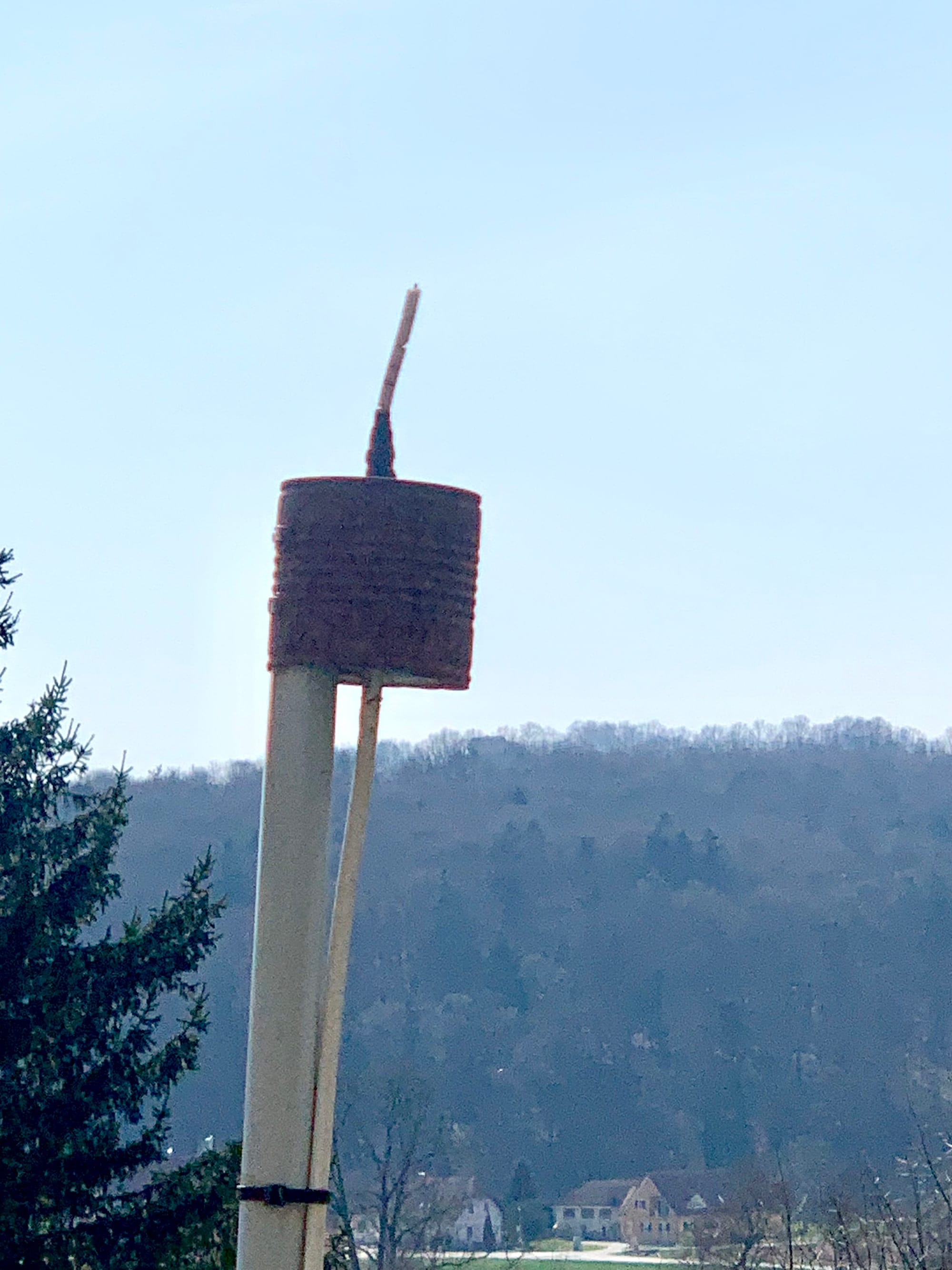
Later it was replaced by a so-called “cantenna”, built from a simple metal can (in this case a bean can). The antenna is installed outdoors and has been operating reliably for several years. However, it is now showing signs of corrosion and will likely need to be replaced in the near future.
For the feedline, a double-shielded satellite coax cable from a local hardware store is used. Despite its simplicity, it provides sufficiently low loss for the relatively long cable run.
Software (initial setup)
For a long time the receiver was operated on a Windows PC using:
- rtl1090 as the ADS-B decoder
- Virtual Radar Server for visualization
Data was forwarded to adsbhub.org.
24/7 Receiver Setup
When moving to a permanent 24/7 receiver, the hardware was changed to a Raspberry Pi 4. The current software stack consists of:
- dump1090 for decoding ADS-B messages
- tar1090 for the web-based aircraft map
- graphs1090 for reception statistics and system monitoring
Today the receiver feeds data to ADS-B Exchange, and the aircraft map embedded on this website is provided directly from ADS-B Exchange.
Technical Overview
DCF77 Time Signal
DCF77 is a longwave time signal transmitter located in Mainflingen, Germany, operating at 77.5 kHz. It broadcasts the official time provided by the Physikalisch-Technische Bundesanstalt (PTB).
Every minute, 59 bits are transmitted using amplitude modulation:
- 100 ms pulse → 0
- 200 ms pulse → 1
The signal contains:
- Time and date
- Day of week
- Daylight saving information
- Error-checking parity bits
Additional services, such as Meteotime weather data, are also embedded in the transmission.
Reception is implemented using a DCF77 receiver module with ferrite antenna and a Raspberry Pi Zero 2 W.
The visualized data is shown here: 👉DCF77 Live
⏱️ Decoding the Time Signal
The DCF77 time signal is decoded by measuring the duration of the amplitude drops once per second:
- ~100 ms → binary 0
- ~200 ms → binary 1
A full minute consists of 59 bits, followed by a missing pulse marking the start of the next minute. The received bit stream is then:
- grouped into time fields (minute, hour, date)
- checked using parity bits
- converted from BCD into human-readable time
Decoding Meteotime Weather Data
In addition to time information, DCF77 also transmits Meteotime weather data.
The data is embedded in the normal signal and distributed over multiple minutes, forming structured data blocks. These blocks contain encoded forecasts such as:
- Weather conditions (sun, rain, clouds)
- Temperature trends
- Regional forecasts for several days
Unlike the time signal, Meteotime data is encoded and partially encrypted, requiring more advanced decoding.
👉 A dedicated decoder reconstructs the data stream, verifies it, and converts it into human-readable weather information.
🔗Additional technical notes on the DCF77 Meteotime reception, frame assembly, and live decoder integration are available here: 👉 Meteotime Decoding – Details
Live Data Receiving
The live implementation demonstrates the full decoding chain from the raw DCF77 signal to usable weather information. A Raspberry Pi continuously samples the incoming signal, reconstructs the bitstream in real time and extracts both the time data and the Meteotime weather frames. The decoded information is written to a lightweight JSON interface and transferred to a web server, where it is visualized and updated every second second. This setup allows direct observation of signal quality, synchronization behavior and the Meteotime decoding process as it happens. More details are availbale here: 👉 DCF77 Live – Details
Receiving HFDL
High Frequency Data Link (HFDL) is a digital communication system used by aircraft to exchange messages with ground stations over long distances. Unlike ADS-B, which relies on line-of-sight at 1090 MHz, HFDL operates on shortwave frequencies (HF) and allows reception of aircraft communications across continents and oceans.
With a suitable SDR receiver and an HF-capable antenna, it is possible to receive HFDL traffic from aircraft thousands of kilometers away. The system is particularly interesting because it provides insight into long-haul aviation routes far beyond local airspace.
A good introduction to HFDL reception can be found here:
https://www.rtl-sdr.com/dumphfdl-a-multichannel-hfdl-decoder-for-sdr/
Hardware
The HFDL receiver is based on an SDRplay RSPdx, which offers better dynamic range and HF performance compared to simple RTL-SDR devices.
The receiver is connected to a Raspberry Pi and operated in headless mode for continuous 24/7 reception.
Antenna
The antenna is a simple HF wire antenna installed outdoors.
Due to the nature of HF propagation, antenna placement and noise environment have a significant impact on reception quality.
Even with a relatively simple antenna, reliable reception of multiple HFDL ground stations across Europe and beyond is possible.
Software
The decoding is performed using:
- dumphfdl for demodulation and decoding of HFDL signals
- SoapySDR interface for SDRplay support
The decoded messages are processed by a custom Python script, which extracts aircraft positions and converts them into a GeoJSON format.
Visualization
Aircraft positions derived from HFDL messages are displayed on an interactive map on this website.
The map is based on Leaflet and uses periodically updated GeoJSON data generated from the receiver.
Unlike ADS-B, updates are less frequent and positions may be less precise, as they are based on reported data rather than continuous broadcasts.
Technical Overview
APRS Station
The APRS station is based on a WX3IN1 Plus 2.0, operating primarily as an APRS-IS client over the local network.
Overview
The device collects "environmental data" (e.g. room temperature 😄 and supply voltage) and periodically transmits beacon packets directly to the APRS-IS network. Although RF operation is possible, most operation is currently done via Ethernet.
Architecture
- Controller: WX3IN1 Plus 2.0
- Network: Static IP in local LAN
- APRS uplink: APRS-IS (Internet-based)
- Beaconing: Periodic position + weather data
- RF path: Optional / secondary (not required for operation)
Operation Mode
The station is configured to send beacons directly to APRS-IS servers (e.g. rotate.aprs2.net:14580).
This allows reliable operation without depending on local RF coverage or nearby digipeaters.
In this mode:
- Position and "weather data" are transmitted at regular intervals (e.g. every 30 minutes)
- No RF reception is required for visibility on APRS services
- Data appears on platforms like aprs.fi almost immediately
Beacon Structure
A single combined beacon is used, containing:
- Timestamp (UTC)
- GPS position
- Station comment
- Weather data (e.g. temperature)
The APRS symbol is explicitly set to a house icon, representing a fixed home weather station.
Notes
- The system is ready to operate with RF gating, but is now used for 24/7 operation via LAN
- Using APRS-IS reduces packet loss and simplifies setup
- RF functionality remains available if needed