LF and HF Utility Monitoring
See also: VHF/UHF radio monitoring →
This page documents receiving and decoding utility signals from LF through HF.
The local setup is mainly based on an Icom IC-7300 connected to a 40 m Windom
antenna installed about 10 m above ground, with approximately 12 m of coaxial
cable. SDR receivers are also used for spectrum monitoring, signal comparison
and software-based decoding.
In addition to the local station, public web-based receivers such as KiwiSDRs
are useful for comparing reception from different locations and for decoding
experiments. They can help to verify whether a signal is active, compare
propagation conditions and provide a convenient audio source for external
decoder software.
The aim is not to provide a complete frequency database, but to document
selected reception examples, receiver settings, decoding software and practical
results. The examples below are ordered roughly from the lowest frequencies
upwards.
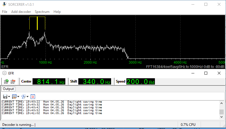
EFR Longwave Telecontrol
EFR is a longwave radio control system used for energy management, tariff switching, load control, heat pumps, storage heaters and similar applications. The signals are transmitted on longwave and are a good example of non-voice LF utility signals that can be observed with a general coverage receiver or SDR.
Signal type
| Parameter | Value |
|---|---|
| Typical frequencies | 129.1 kHz, 135.6 kHz, 139 kHz |
| Mode | FSK |
| Approx. bandwidth | about 1 kHz |
| Content | Telecontrol and time-synchronised control data |
| Reception | LF / longwave, best with low noise and stable receiver |
EFR lists 129.1 kHz, 135.6 kHz and 139 kHz as carrier frequencies for its longwave receiver system, and the signal is FSK-modulated.
Used software
SDR software is mainly used for observing the signal in the waterfall and checking signal strength. For decoding experiments, software such as MultiPSK, Sorcerer or dedicated signal analysis tools can be used.
Screenshot
DWD LF RTTY on 147.3 kHz
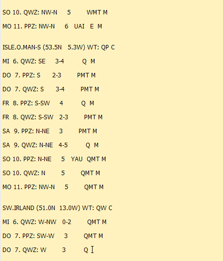
The German Weather Service also transmits marine weather information by RTTY on longwave. This is an interesting signal because it combines LF propagation with a classic narrowband teleprinter mode.
Signal type
| Parameter | Value |
|---|---|
| Frequency | 147.3 kHz |
| Station | DDH47 |
| Mode | F1B RTTY |
| Speed | 50 baud |
| Shift | ±42.5 Hz |
| Content | Marine weather reports and warnings |
The DWD schedule lists DDH47 on 147.3 kHz with 50 baud F1B and ±42.5 Hz shift.
Official schedule and information: DWD – Funkausstrahlung Sender Pinneberg
Used software
Fldigi, MultiPSK or similar RTTY-capable software can be used. The receiver should be stable and the audio level should be adjusted carefully, because the narrow shift makes tuning more critical than with wider HF RTTY signals.
Screenshot
Aeronautical NDB Morse Beacons
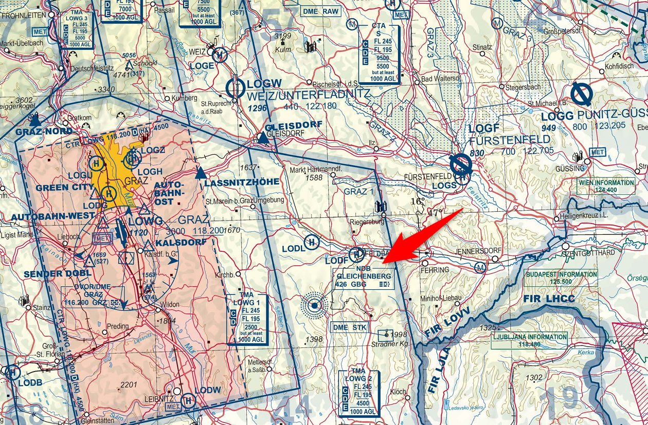
Non-directional beacons are still interesting monitoring targets, even though many have disappeared from active aviation use. They transmit a continuous carrier with a Morse identifier and can often be received over surprisingly long distances during good LF/MF conditions.
Signal type
| Parameter | Value |
|---|---|
| Typical range | roughly 190–535 kHz for many aviation NDBs |
| Modulation | carrier with 400 Hz or 1020 Hz audio identification |
| Content | Morse identifier, sometimes additional voice/weather information |
| Bandwidth | narrow, usually well below 1 kHz for the identifier |
FAA information describes NDBs as low- or medium-frequency beacons normally operating in the 190–535 kHz range, transmitting a continuous carrier with 400 Hz or 1020 Hz modulation and Morse identification.
A list of NDB beacons can be found in Wikipedia - Liste der ungerichteten Funkfeuer which are also shown on a map. For Austria there is also a free download of the ICAO map: Austro Control GmbH - Digitale Version der Luftfahrtkarte
Used software
The signal can be identified by ear, by waterfall, or with a CW decoder. SDR-Console, SDR++, fldigi CW, CwGet or similar tools can be used.
Screenshot
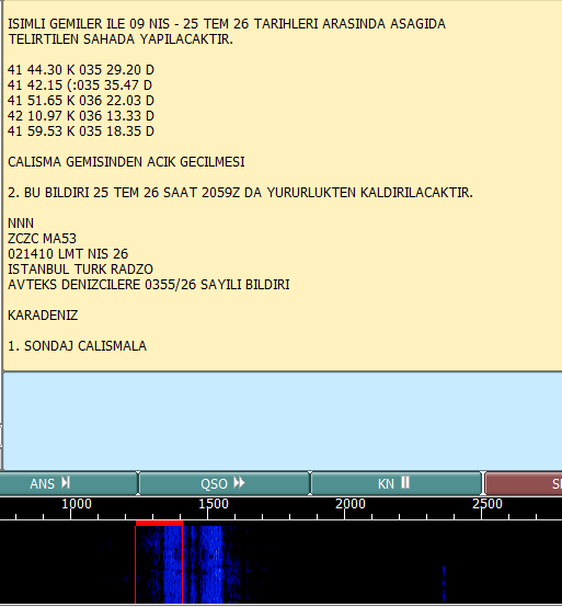
NAVTEX Maritime Safety Messages
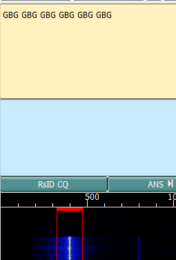
NAVTEX is one of the most useful and practical utility signals to decode. It carries maritime safety information, navigational warnings, meteorological warnings and forecasts.
Signal type
| Parameter | Value |
|---|---|
| Main international frequency | 518 kHz |
| National / local language frequency | 490 kHz |
| HF NAVTEX / MSI frequency | 4209.5 kHz |
| Mode | SITOR-B / FEC |
| Modulation | FSK |
| Speed | 100 baud |
| Shift | 170 Hz |
| Recommended receiver bandwidth | about 270–340 Hz |
NAVTEX uses 100 baud FSK with 170 Hz shift; 518 kHz is the international frequency, with 490 kHz and 4209.5 kHz also used for certain services.
Used software
Fldigi supports NAVTEX/SITOR-B decoding. Other useful tools include YaND and MultiPSK.
Screenshot
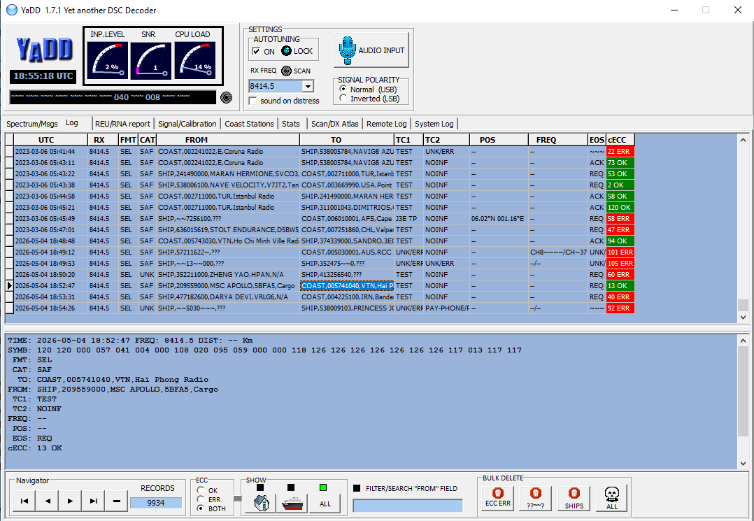
GMDSS / DSC Maritime Calls
Digital Selective Calling is part of the Global Maritime Distress and Safety System. It is normally used for automated calling, distress alerting and maritime coordination. For a receiving station, DSC is interesting because it is compact, structured and easy to recognise in the waterfall.
Signal type
| Parameter | Value |
|---|---|
| MF/HF distress and safety frequencies | 2187.5, 4207.5, 6312, 8414.5, 12577, 16804.5 kHz |
| Mode | F1B / J2B |
| Speed | 100 baud |
| Shift | 170 Hz |
| Audio centre frequency | 1700 Hz |
| Content | Maritime DSC calls, identifiers, safety/distress-related signalling |
ITU-R M.493 specifies 170 Hz shift and 100 baud for MF/HF DSC channels, and common MF/HF DSC frequencies include 2187.5 kHz, 4207.5 kHz, 6312 kHz, 8414.5 kHz, 12577 kHz and 16804.5 kHz.
Used software
YADD, MultiPSK, SeaTTY or other DSC decoders can be used. SDR software is useful to keep several DSC channels visible and to check propagation.
Screenshot
HF Time and Frequency Stations
Time signal stations are very useful as propagation indicators and receiver frequency checks. They are also easy to recognise because of their fixed schedules, tones, pulses and station identifiers.
Signal type
| Station | Frequencies | Notes |
|---|---|---|
| WWV | 2.5, 5, 10, 15, 20 MHz | US time and frequency standard |
| CHU | 3330, 7850, 14670 kHz | Canadian time station with digital time code |
| RWM | 4996, 9996, 14996 kHz | Russian time signal station |
NIST lists WWV on 2.5, 5, 10, 15 and 20 MHz; CHU transmits on 3330, 7850 and 14670 kHz using AM-compatible modulation; RWM is commonly listed on 4996, 9996 and 14996 kHz.
Used software
Usually no special decoder is required. SDR software, an audio recorder and a frequency display are sufficient. For CHU, the digital time code can also be decoded experimentally.
Screenshot
Insert screenshot: RWM or WWV carrier, time ticks and audio spectrum.
HF VOLMET Aviation Weather Broadcasts
VOLMET broadcasts provide weather information for aircraft in flight. They are voice transmissions, but still belong to the utility monitoring world because they are scheduled, operational broadcasts rather than entertainment or broadcast radio.
Signal type
| Parameter | Value |
|---|---|
| Example station | Shannon VOLMET |
| Frequencies | 3413, 5505, 8957, 13264 kHz |
| Mode | USB voice |
| Bandwidth | approx. 2.8–3 kHz |
| Content | Aviation weather, METAR/TAF-style reports |
AirNav Ireland lists Shannon VOLMET on 3413, 5505, 8957 and 13264 kHz.
Used software
No decoder is required. SDR-Console, the IC-7300 audio output, an audio recorder or transcription tools can be used to document reception.
Audio Samples
Russian Single-Letter Channel Markers
Single-letter beacons, also known as channel markers or cluster beacons, transmit repeated Morse letters on several HF frequencies. They are useful for propagation observation and signal identification practice.
Signal type
| Parameter | Value |
|---|---|
| Example clusters | around 3594, 4558, 5154, 7509, 8495, 10872 kHz |
| Mode | CW / OOK Morse |
| Content | repeated single-letter identifiers |
| Bandwidth | very narrow |
Priyom describes these as single-letter beacons clustered in 100 Hz slots, with not all channels active at all times.
Used software
The signals can be copied by ear, with a CW decoder, or simply documented in the waterfall. SDR software is especially useful because several markers can appear very close together.
Audio Sample
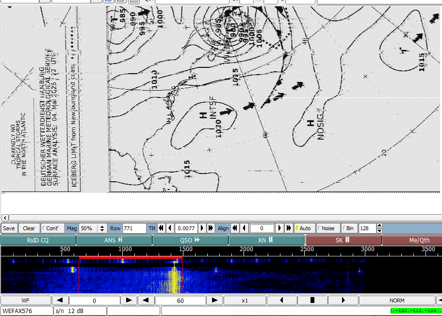
DWD / Pinneberg Weather Fax
Weather fax is one of the most visually rewarding HF utility modes. The received signal is decoded into weather charts, pressure maps, wave forecasts or ice charts.
Signal type
| Parameter | Value |
|---|---|
| Station | DWD / Pinneberg DDH / DDK |
| Frequencies | 3855, 7880, 13882.5 kHz |
| Mode | F1C radiofax |
| Typical fax setting | 120 lpm / IOC 576 |
| Content | Weather charts for maritime use |
The DWD schedule lists weather fax transmissions from Hamburg/Pinneberg on 3855 kHz, 7880 kHz and 13882.5 kHz, with typical 120/576 fax parameters.
Used software
Fldigi, SeaTTY, JVComm32 or similar weather fax software can be used. With an SSB receiver, the dial frequency may need to be offset so that the fax tones fall correctly into the decoder audio passband.
Screenshot
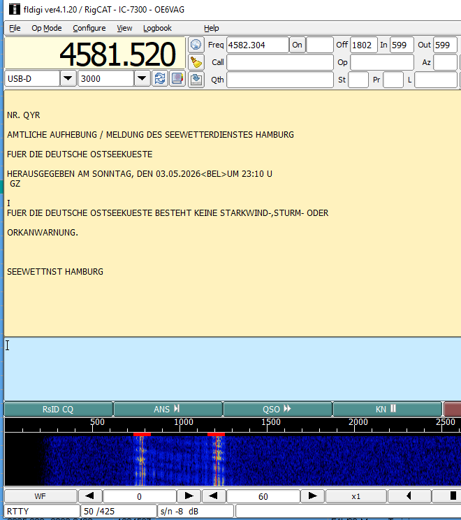
DWD / Pinneberg HF RTTY Weather Telex
In addition to fax charts, DWD transmits text-based marine weather information by RTTY. These transmissions are good practical examples of classic HF FSK decoding.
Signal type
| Parameter | Value |
|---|---|
| Example frequencies | 4583, 7646, 10100.8, 11039, 14467.3 kHz |
| Mode | F1B RTTY |
| Speed | 50 baud |
| Shift | typically ±225 Hz on HF |
| Content | Marine weather reports, warnings and forecasts |
The DWD RTTY schedule lists several HF channels, including 4583 kHz, 7646 kHz, 10100.8 kHz, 11039 kHz and 14467.3 kHz, mostly with 50 baud and ±225 Hz shift.
Used software
Fldigi and MultiPSK are suitable for decoding. If the text appears inverted or garbled, the signal polarity or sideband setting may need to be changed.
Screenshot
STANAG and MIL-STD HF Data Signals
A large number of HF utility signals are not intended for public decoding. Many
of them use standardised military or governmental data waveforms, for example
STANAG or MIL-STD based HF modem signals. These transmissions are often found
across the HF spectrum and are usually encrypted or otherwise not readable
without the proper equipment and authorisation.
For this monitoring station, these signals are documented only from a technical
and observational point of view. The aim is to identify the signal type, occupied
bandwidth, modulation characteristics and waterfall appearance — not to decode
or interpret protected message content.
Signal type
| Parameter | Value |
|---|---|
| Service type | Military, governmental and professional HF data links |
| Typical frequency range | HF spectrum, roughly 2–30 MHz |
| Common waveform families | STANAG, MIL-STD-188 and similar HF modem standards |
| Modulation | usually PSK-based digital modulation |
| Typical bandwidth | often around 3 kHz, depending on waveform |
| Content | usually encrypted or otherwise not publicly decodable |
| Receiver mode | USB, depending on tuning and decoder setup |
Used software
SDR software is mainly used to observe these signals in the waterfall and to
measure their approximate bandwidth and centre frequency. Signal analysis tools
can help to recognise typical waveform patterns, symbol rates or idle sequences.
In most cases, no message content is decoded. The documentation is limited to
signal characteristics such as frequency, time of reception, bandwidth, visible
waterfall pattern and general classification as an HF data modem signal.
More info: https://www.udxf.nl/Some-Notes-on-STANAG4285.pdf
Screenshot
Insert screenshot: STANAG / MIL-STD style HF data signal in the waterfall,
showing the occupied bandwidth and modulation pattern.
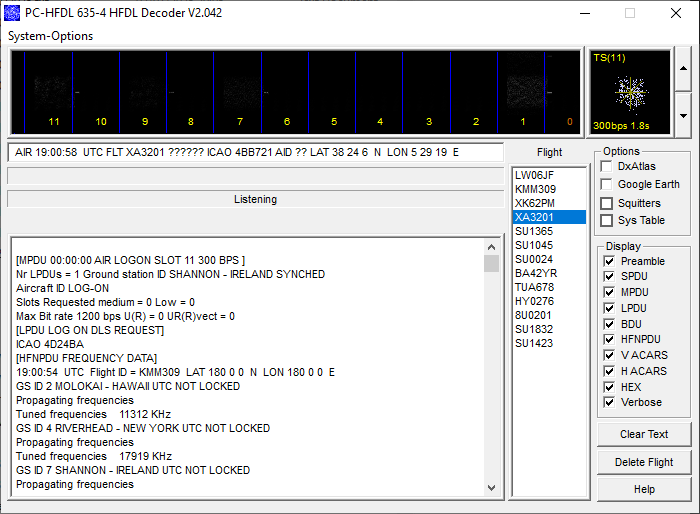
HFDL / HF Aircraft Data Link
HFDL is a digital aeronautical data link used by aircraft and ground stations on HF. It can carry ACARS/AOC messages, CPDLC and ADS-C position reports. When decoded successfully, aircraft positions can be displayed on a local map.
Signal type
| Parameter | Value |
|---|---|
| Frequency range | HF aviation bands |
| Modulation | PSK2 / PSK4 / PSK8 |
| Symbol rate | 1800 baud |
| Approx. occupied bandwidth | about 400 Hz |
| Content | Aircraft data link messages and position reports |
The dumphfdl project describes HFDL as a protocol for aircraft-to-ground-station communication on HF, carrying ACARS/AOC, CPDLC and ADS-C messages; technical references list PSK2/4/8 modulation, 1800 baud and about 400 Hz bandwidth.
Used software
For this station, dumphfdl and PC-HFDL are the preferred decoders. SDR software is used to choose active channels and monitor signal quality. Decoded aircraft positions can be converted into GeoJSON or displayed on a local map.
For live decode on this website see HFDL.
Screenshot
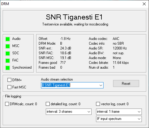
DRM Shortwave Broadcasts
DRM, Digital Radio Mondiale, is technically a broadcast system rather than a utility service, but it fits well on this page because it is a digital HF signal that requires software decoding and careful receiver setup.
Signal type
| Parameter | Value |
|---|---|
| Frequency range | Longwave, medium wave and shortwave broadcast bands |
| Typical HF bandwidth | 9 or 10 kHz |
| Modulation | COFDM |
| Content | Digital audio, text and data services |
| Reception requirement | stable receiver, sufficient bandwidth, good SNR |
DRM is designed for the AM broadcast bands below 30 MHz and typically uses 9 or 10 kHz bandwidth, with COFDM modulation and digital audio/data services.
Transmission schedules may be found in Deutsches DRM Forum - DRM-Programme und -Verbreitung bis 30 MHz
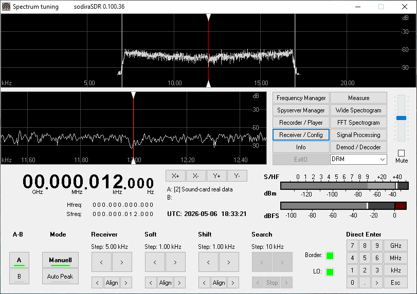
Used software
Dream and SodiraSDR are a common DRM software receivers for Windows. JvanKatwijk or qt-drmplus are also good choices. SDR software with suitable bandwidth and stable tuning is required. DRM reception is very sensitive to fading and frequency accuracy, so screenshots of the decoder status are useful.
Note for the IC-7300: under SET > Connectors > ACC/USB Output Select set the output to IF
Screenshot
FT8 Amateur Radio Propagation Monitoring
FT8 is not a utility service in the strict sense, but it is included here as a
very useful amateur radio mode for checking HF propagation conditions and the
performance of the receiving station. Because many stations worldwide transmit
FT8 almost continuously on fixed dial frequencies, the mode is well suited for
comparing reception conditions on different HF bands.
With the IC-7300 and the 40 m Windom antenna, FT8 signals can be received on
several amateur bands. Even weak signals, often far below the noise level by
ear, can be decoded by the software. This makes FT8 a practical tool for
observing band openings, antenna performance and day/night propagation changes.
Signal type
| Parameter | Value |
|---|---|
| Service | Amateur radio |
| Mode | FT8 |
| Modulation | 8-tone FSK / digital weak-signal mode |
| Typical bandwidth | about 50 Hz per signal |
| Transmission cycle | 15 seconds |
| Content | Callsigns, locator, signal reports and short standard messages |
| Receiver mode | USB |
| Typical HF dial frequencies | 3.573, 7.074, 10.136, 14.074, 18.100, 21.074 and 28.074 MHz |
Used software
WSJT-X is used for decoding FT8 signals. JTDX can also be used as an
alternative decoder. The IC-7300 can be connected directly to the computer via
USB audio, while SDR receivers can be used in parallel for spectrum monitoring.
For visualising received stations and propagation paths, tools such as
GridTracker or PSK Reporter are useful.
A typical screenshot can show the WSJT-X waterfall, the decoded messages and,
if available, a map of received stations. This gives a good overview of the
current propagation situation on the selected band.
Screenshot
Insert screenshot: WSJT-X waterfall and decoded FT8 messages on one of the HF
amateur bands.
Optional second screenshot: GridTracker or PSK Reporter map showing received
stations and propagation paths.
SSTV Amateur Radio Image Transmissions
SSTV, or Slow Scan Television, is an amateur radio image transmission mode used
to send still pictures over narrowband radio channels. Although it is not a
utility service in the strict sense, it is included here as an interesting
example of software-based signal decoding on HF and VHF.
With the IC-7300 and the 40 m Windom antenna, SSTV signals can be received on
several HF amateur bands. The received audio is fed into decoding software,
which reconstructs the transmitted image line by line. Depending on propagation,
signal strength and interference, the resulting image may range from almost
perfect to heavily distorted — which makes SSTV a very visual way of documenting
HF reception conditions.
Signal type
| Parameter | Value |
|---|---|
| Service | Amateur radio |
| Mode | SSTV |
| Modulation | Analogue audio tones over SSB or FM |
| Typical HF receiver mode | USB |
| Typical bandwidth | approx. 2.5–3 kHz |
| Common modes | Martin M1, Scottie S1, Robot, PD modes |
| Content | Still images, callsigns, captions, QSL-style pictures |
| Typical HF activity frequencies | 3.730, 7.171, 14.230, 21.340 and 28.680 MHz |
| VHF example | 145.800 MHz FM for ISS SSTV events, when active |
Used software
SSTV can be decoded with programs such as MMSSTV, QSSTV, RX-SSTV or Robot36.
The IC-7300 can provide the audio directly via USB, while SDR software can also
be used to monitor the signal in the waterfall.
A useful documentation example is a screenshot showing the SSTV decoder while
the image is being reconstructed, together with the final received picture.
This gives a clear visual impression of both the signal quality and the decoding
result.
Screenshot
Insert screenshot: SSTV decoder window showing a received image and the
corresponding waterfall or audio spectrum.